Note: Do NOT heat the landing gear legs above 300°F as this could alter the heat treatment. We advise against Powder coating the legs as the will typically be heated above 350°F
Note: The P8903 landing gear are machined from 7075-T6 aluminum. 7075-T6 is more sensitive to "notches" (tool marks, scratches,etc see step 1.) than lower strength aluminum's. It is also less corrosion resistant and needs to be painted ,or polished frequently to control corrosion. We recommend scuffing, etching and priming with epoxy type primer (following primer manufactures suggestion) before installing, then painting the legs later along with the rest of aircraft.
1.The P8903 tri gear legs come pre-machined and drilled, however, they need to be de-burred and the edges and tool marks polished out. There are usually tool marks, particularly on the trailing edge, and some sharp edges that need to smoothed out. A random orbit sander with several grits (150,220,320) of paper works well, for this. Finish to a minimum of "320 grit". Use caution not to change the size or basic shape, just remove tool marks scratch etc and slight debut the edges.
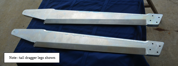
2. Prime P8903 landing gear per "Note" Above
3. Trim the P8908 radius blocks to 6" long.
4. using 2 "c" clamps,Clamp them securely in place on the lower landing gear plates in the fuselage,with the top edges flush.See photo below
5. "Transfer Drill" the P8908 radius blocks through the fuselage plates with a 5/16 drill bit
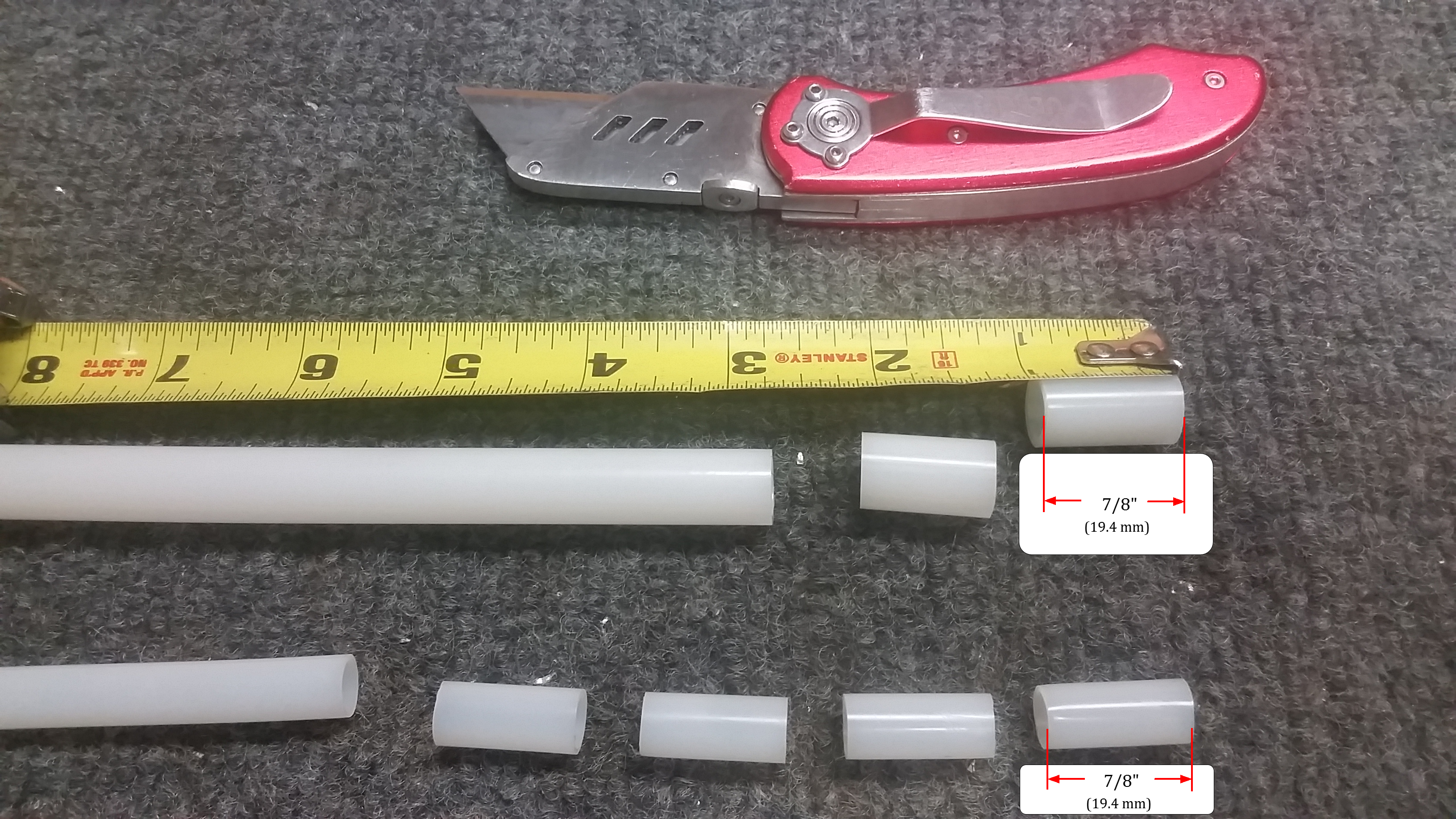
6. Cut qty 4, Nylon bushings 7/8"L from the 3/8" OD x 5/16" ID nylon tube stock (McMaster -Carr # 8628K28) and insert 1 each into the 3/8" dia lower landing gear mount holes of the gear leg.
7. Cut qty 2, Nylon bushings 7/8 "L from the 1/2" OD x 7/16" ID nylon tube stock (McMaster-Carr #8628K55) and insert 1 each into the 1/2 inch upper hole of the gear legs.
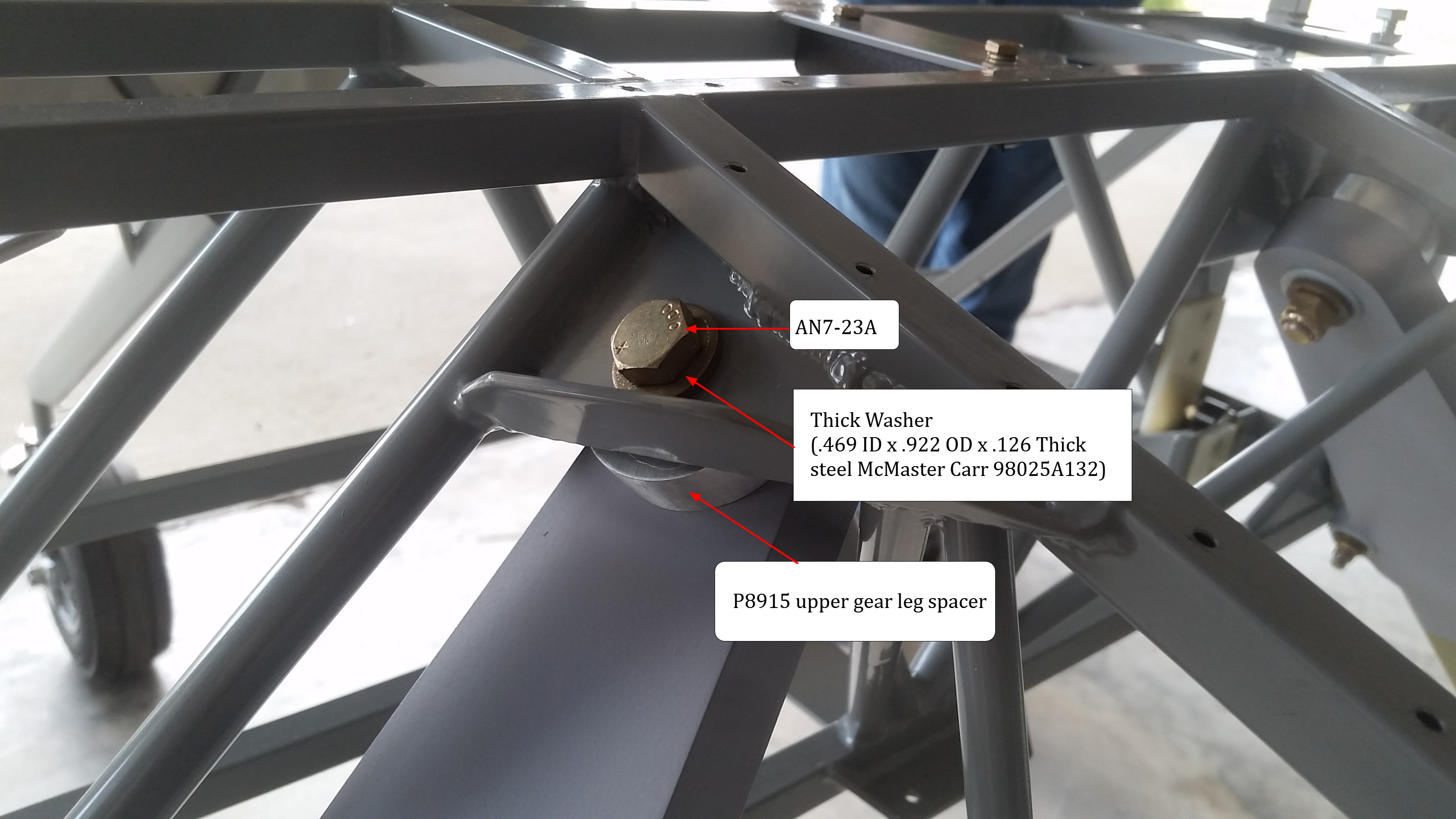
8. Place landing gear leg and P8908 radius onto fuselage and install upper and lower hardware per photos (below). A second person to hold things is helpful
Torque AN365-720A nuts (upper bolts)(7/16-20 thread) 450-500 In-Lbs or37-42 Ft Lbs
Torque MS21042-5 nuts ( lower bolts) (5/16-24 threads) 100-140 In-Lbs or 8-12 Ft-Lbs

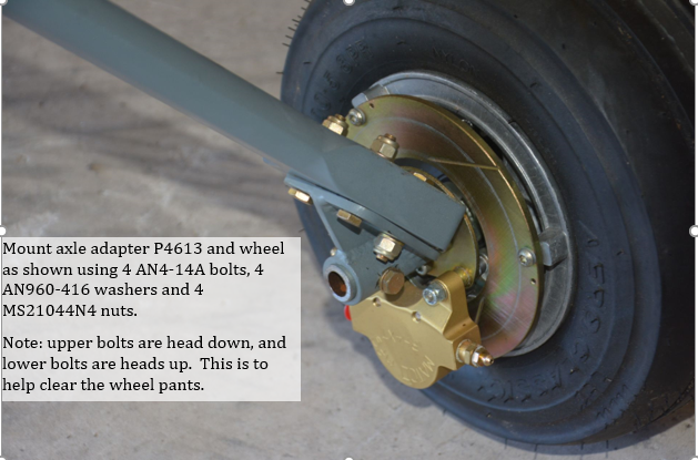
9. Install the P8613 Landing Gear Axle Adapters with qty 4 , AN4-14A and temporary nuts (these will be removed for drilling the axel cross bolt)
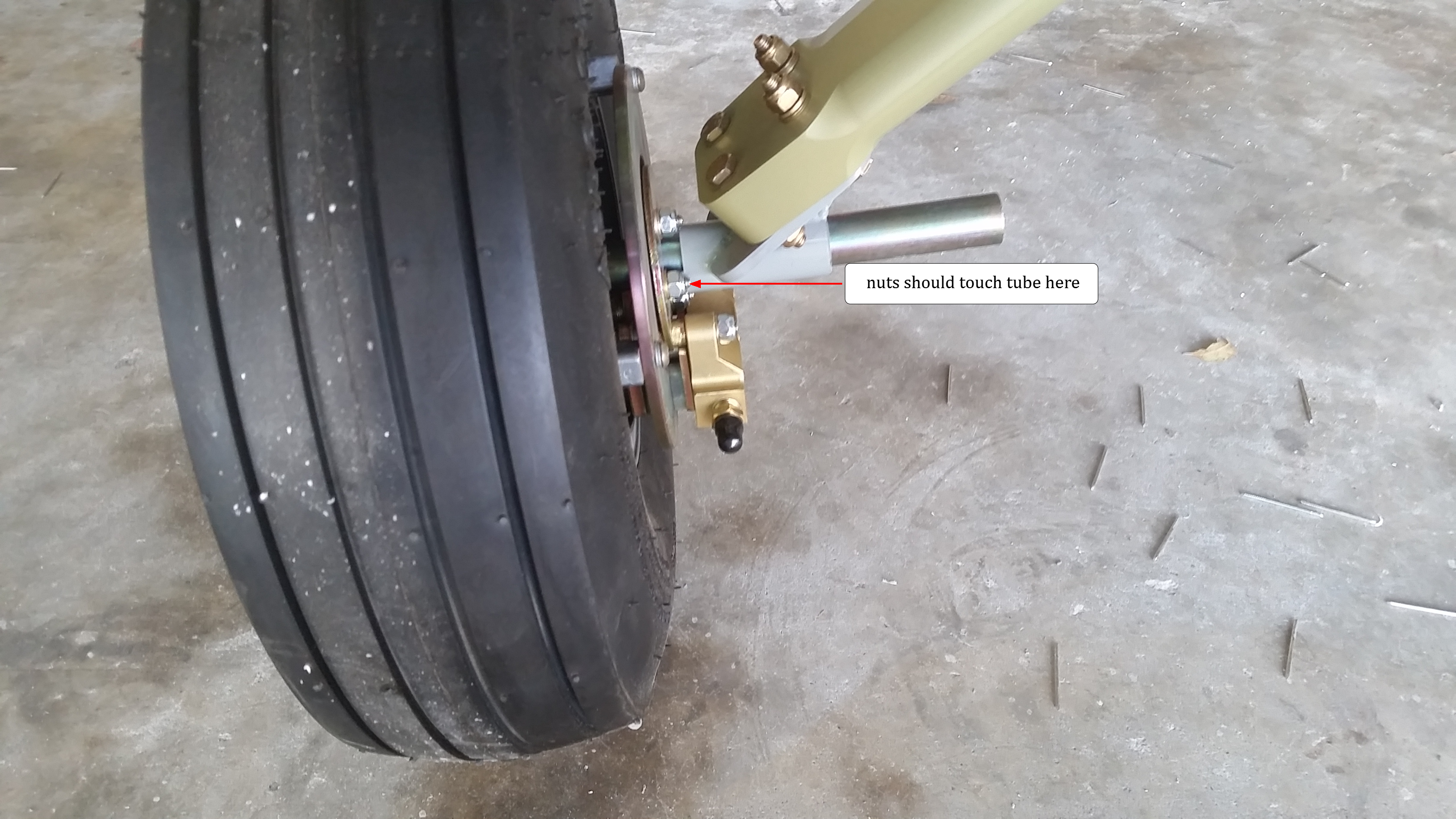
10. Slide axle into the adapters until the backing plate nuts touch the "adapter tube" Brakes should be on the bottom to clear the wheel pants. The standard Matco axle that SPA offers is used for both the smaller 11x4.00-5 tires and the larger 11x5-5.00 tires.
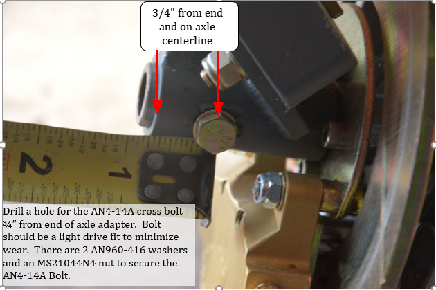
11. Remove the Axle adpater /axle /wheel assembly at the gear leg , trim and drill the axle per photo below for the AN4-14A cross bolt. Axles should be a "snug" fit into the axle adapter . We suggest using a drill press for this.Bolt holes should be drilled for a light drive fit, to minimize bolt wear.
10. Install P8613 Landing Gear Axle Adapters onto the gear leg per photo , if installing wheel pants you may want to add the P9501 wheel pant brackets at this time (See Wheel Pant Installation )