
Wow, I can’t believe it was over 4 years ago that I wrote the first (and only) Cougar Designer’s Desk post. It would take an entire post to cover all the things that have transpired in my life – with SPA, family, and personally, so I will just say that it has been a lot and get onto this post.
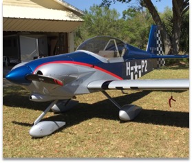
Anyone who came by our booth at Oshkosh 24 (Air Venture) this year was able to see some parts of the Cougar airframe. If you are wondering what a Cougar is, because it’s been so long, don’t feel bad – sometimes I have the same problem. You can go back and review Cougar Designers Desk 1 for a refresher Cougar Designer’s Desk #1 Post. Since CDD1 we have made substantial progress on the design and tooling for the Cougar prototype. The tail cone and empennage have been finalized and built. The forward fuselage ‘cage’ has been modified at least 4 times for minor and major tweaks to cockpit leg room, ergonomics, and center of gravity. The main wing spar carry through is machined and fitted, and the tooling for the left wing and fuel tank machined and tested. The weeks leading up to OSH 24 we built the first Cougar wing to be used for structural testing.
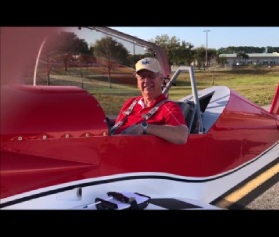
Here is a quick walkaround video clip of the prototype as displayed at OSH ’24.
While at OSH 24, we said we were going to do the wing, horizontal and vertical tail structural testing in September. I am happy to report that we completed the testing and met a Cougar deadline – FINALLY! The testing was completed over approximately 3 weeks of ‘spare time, with a lot of help from some incredibly good friends. We did have a few ‘scratch our heads’ moments as we worked through testing the wing. The Cougar wing test method was a little different than how we tested the Panther wing. While working with more than 7,000 lbs. of sand and a combined force of over 15,000 lbs., we had some very real concerns about safety, and it was incredibly stressful at times! When the sandbags settled, we learned a lot, had very sore backs, and I am happy to report that the tests were successful!

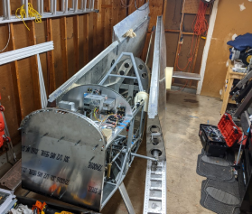
The wing testing was accomplished with the left-wing, spar center section, and balance arm fixtured to a 16” I beam upside down and tilted to simulate the lift vector. The beam was anchor bolted to the floor to reduce fixture bending and allow accurate deflection measurements. On the opposite side of the wing was a balance arm bolted to the spar center section. This arm was connected to a hydraulic cylinder and an industrial crane scale so we could adjust the force. This allowed us to test without the expense and time of building a second (right) wing, that would end up going to the scrap yard. The balance beam concept also allowed us to easily change the force to accommodate both symmetrical and asymmetrical loading cases across the center spar section. Not having to stack 7,000 lbs of sand on the second wing was also a plus!

In the Panther testing, we had some issues controlling the sandbags and, in the end, we were not able to test the wing to structural failure because the sandbags shifted, causing some to fall, resulting in damage to some wing ribs before the wing or spar failed. Since we were at a load case significantly higher than the ultimate load, which is equivalent to 9Gs, we accepted the outcome and pledged to figure out a better/safer way, with more control.
For the Cougar test we laminated, and then hot wire cut 5 polystyrene foam blocks to create 11 load bays. These were attached to the wing with foam double-sided tape segments to hold them in place, but not add any rigidity. This created a level platform for the sandbags to sit on.

I should add a quick and simplified explanation of the same basic terms.
Design load = the calculated maximum load without any safety factor.
Ultimate Load = the calculated maximum load with safety factors.
For ‘metal’ aircraft the industry standard minimum is design load x 1.5 = Ultimate load. The Cougar design load factor at aerobatic weight is 6Gs so the Ultimate load is 9Gs. Some specific parts are subject to additional safety factors. Bolted joints typically have 1.5 x1.2=1.8 safety factors. Parts made from castings, control surface balance weights, and other components also have additional safety factors.
FAA FAR regulations for aircraft design, ASTM for LSA design, and many light aircraft design materials specify the structure must be designed so that it can support the design load without permanent deformation or damage. From the design load to the ultimate load the structure may permanently deform but still must be able to support the load.
Symmetric loading= For the wing, and horizontal tail the force is equal on both sides.
Asymmetric loading = the load is 100% on one side and reduced on the other. Typically, this is 100%/70%. The Cougar is designed for Aerobatics, so we used 100%/60% as a starting point. Because we started at 60% on the balance arm cylinder and 100% on the wing, then slowly increased the cylinder force to 100% we effectively tested the entire range between 60% and 100%
We started the test with a 1G load case to season the wing and fixture. We then loaded and unloaded the 2G case. After this we quickly decided that hand loading and unloading each case would mean we needed to load and unload over 32,000 lbs. of sand to complete the test. We decided to build pallets so we could stack and secure the sandbags. We could then carefully set them on and off the foam load block bays/wing with a forklift and lifting straps. This also allowed us to hold the last pallet and gently lower it, ensuring if any failure occurred, the heaviest load would settle and be held by the straps and forklift.

We resumed testing by loading the pallets and applying equivalent force to the balance arm cylinder. When we reached 60% load, we held the force on the balance arm cylinder and slowly lowered the final pallet. This tested the asymmetric loads across the center section spar. We then brought the balance arm force up to 100% and documented the deflections on the wing and balance arm. Then we unloaded the wing and checked the wing and balance arm for damage and that it was not permanently deformed. At the 5G mark we noticed the balance arm was slightly deformed after unloading. We paused testing, did some quick calculations, and confirmed that the arm was not strong enough to complete the tests. We had spent hundreds of hrs. on the wing design but used a much more casual approach to the balance arm design. After adding the necessary strength to the balance arm and testing it independently from the wing to verify was up to the task we repeated the 5G test cases to verify the deflections. Then over the next few days we completed the remaining load cases. (Pic of 8G test)


As we worked through the Cougar wing load test it easily passed the design load (6G) test.
At the 7 G test we noticed some odd deflection. Through inspection we found a nut on the rear spar attach bracket (also the wing fold hinge) had failed. We stopped testing and evaluated.
This area: The first problem was it was designed to have QTY 5 AN3 bolts and only 4 were installed. Also, the loads on the bolts were not evenly distributed so the bolt that was not installed, and the one with failed nut had the highest loads. We installed AN4 bolts in these locations, did a thorough inspection of the entire structure then repeated load case 7 and found no permanent deformation. I should note that the rear spar attach fitting is being redesigned to be more compact as to even out the bolt loading. We will independently load test this in the near future.
8G cases with no permanent deformation.

On the 9G case the wing was permanently damaged but still held the load. In the picture below you can see the wing failed in the outboard 25% of the wing. Early in the wing design I decided I wanted the wing to have the lowest structural margins extremely far out on the wing. The wing buckled exactly where I (and others) expected it would.

Here is a time lapse video of a case load test.
With the wing successfully tested we cut the fixture and built a new fixture to hold the horizontal tail and then the vertical tail.


We hand-stacked these load cases, and it sure made me glad we took the time to make the load pallets for the wing test! We used a hydraulic cylinder and jack to support the structures while loading and unloading the sand.
Both the horizontal tail and the vertical tail completed the 9G cases with no permanent deformation! At 10 and 11 Gs both the horizontal tail and vertical tail had minimal deformation. We stopped testing because the load was getting hard to stack and it was becoming unstable.


In the coming weeks we will cut a series of 4” holes in the wing, horizontal and vertical tails to see what we can learn.
I am incredibly pleased with the results and excited to move forward with building the prototype structures.
It is important to note that the Cougar is being designed with FAR 23 and ASTM LSA aircraft design standards as a guide, however, I am not implying or claiming it meets every standard.
Also important: Currently the Cougar is still a personal project that is being worked on outside of Panther and other production work at SPA.
See the most recent 2D view drawing here – Cougar 2 View
Currently we have no other information to report. Read that as “Please do not call or email asking for more information”. We will post what we have when we make substantial progress or want feedback. I will document the build with regular ‘Designer’s Desk’ or ‘Builders Bench’, and eventually ‘Test Pilots Posts’ as we move along. Rachel will be posting to the website and social media so feel free to leave comments etc. Please understand that we may not be answering all questions at this point so we can concentrate on building. We specifically do not know “how much it will cost” or “When it will be available”!

Planning to have another interesting post much sooner than 4 years from now.
Dan Weseman
Oh no – I may have to build a Cougar after I get my Panther done. That “Cougar 2-view” drawing is about the nicest looking 2-seater I’ve ever seen!
I’m glad my AeroSpace Systems degree left out sand bag loading in the lessons! Any fatigue testing of wing structure planed or is that being ridiculous with our relatively low time toys.
Thank you for the positive update. I know it will be strong and safe. I wish I could be around to build, fly, and teach my grandsons and granddaughter in it.
Bob Foster
Very interesting, congratulations!
Fantastic update post Dan. Was so glad to see the prototype at OSH24 and very happy to see progress on the Cougar. Congrats on the successful load tests! Keep up the great work and good luck with finding time for this side project so many of us are excited for!
Wow. Blessings at you guys. Hope there is a hot tub for y’all’s backs.