The SPA supplied steering linkage is designed to give a simple and attractive appearance (VS springs) and provide accurate positive steering with a bit of shock absorption. The installation method below will pre-load the springs 1 inch. If, after taxing and test flying, a more firm steering feel if desired you can dis-assemble the link and add an equal size spacer to the end of the forward and aft spring. If equal spacers are used the springs will be more compressed, however the link length will not change.
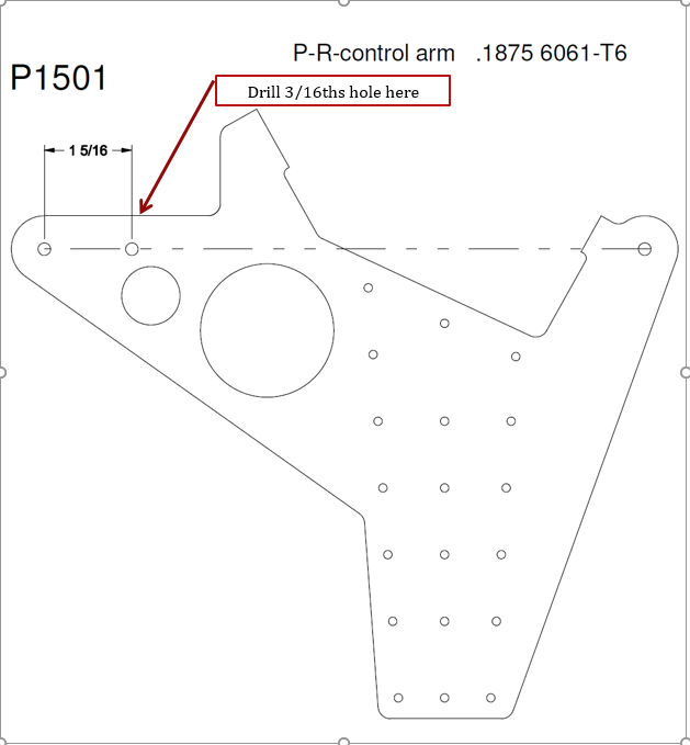
1. Drill a 3/16ths hole as per drawing below
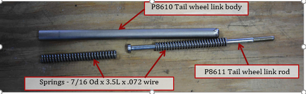
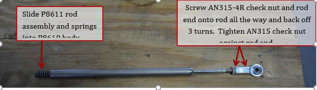
2. The tail wheel link outer body contains the P8610 Body, P8611 Rod, and 2 springs. Slide one of the springs over the tail wheel rod.
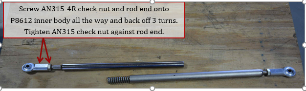
3. Slide the rod assembly and springs into the P8610 tail wheel link body. Screw on the AN315-4R nut and rod end onto the rod all the way on, and then back the rod end off 3 turns. This will leave some adjustment each way. NOTE – you must have a ½” of threads into the rod end body for full strength. Tighten AN315-4R nut against rod end. The picture below shows one spring partially out, in reality it will be entirely in the body.
4. Screw Rod end and AN315-4R check nut onto P8612 Tail wheel link inner body all the way, then back off 3 turns.
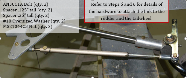
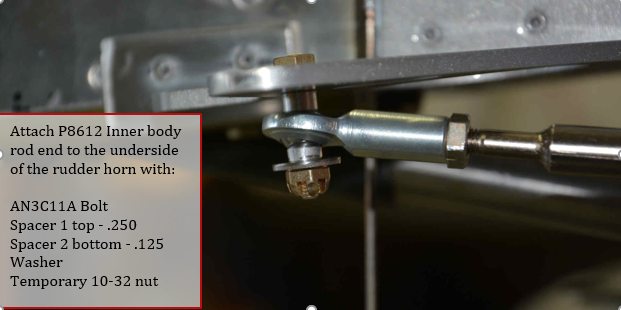
5. Attach P8612 inner body rod end to the underside of the rudder horn. Use a temporary nut as you will have to remove it later.
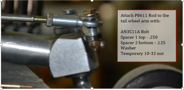
6. Attach outer body and rod to the underside of the rudder horn. Use a temporary nut as you will have to remove it later.
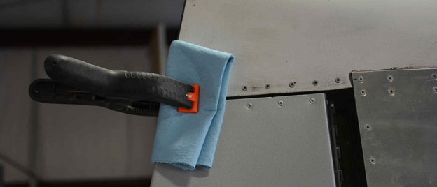
7. Center the rudder and clamp in position.
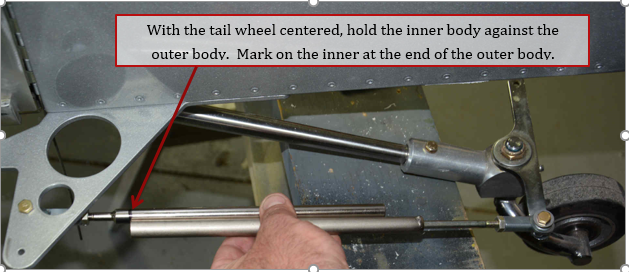
8. With the tail wheel centered hold the outer body and the inner body next to each other. Place a mark on the inner rod at the end of the outer rod. Make sure that the outer body has been pulled tight against the inner spring, but not enough to compress the spring.
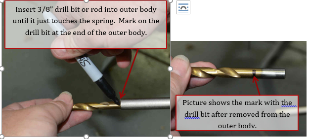
9. Using a 3/8” drill bit or similar rod, insert into the end of the outer body until it just touches the spring. Make sure that the outer body has been pulled tight against the inner spring, but not enough to compress the spring.
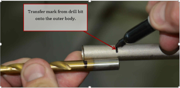
10. Hold drill bit against the end of the outer body, and transfer the mark onto the outer body. This mark defines where the spring ends in the outer body.
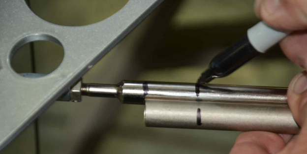
11. Hold inner body against outer body again and transfer mark just made in previous step to the inner body. Make sure the end of the outer body lines up with the mark on the inner body made previously.
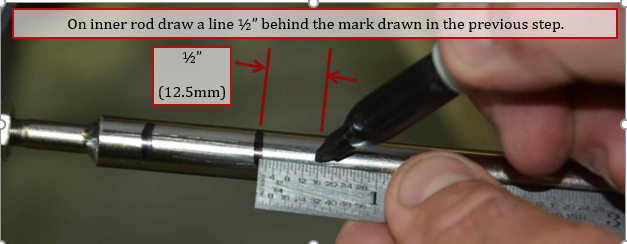
12. On the inner body, make a mark ½” (12.5 mm) behind the mark made in previous step. This will define where to cut the inner body.
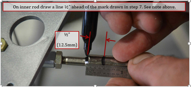
13. On the inner body, make a mark ½” (12.5 mm) ahead of the mark made in step 7 (the mark for the end of the outer body). This will define where the inner body will be compressed to in a later step. Note: Due to variations in the length of the tailwheel spring, your mark may not be at the end of the inner body as shown in the picture below. This just happened to be the way this particular aircraft worked out. Please mark as needed for proper fit.
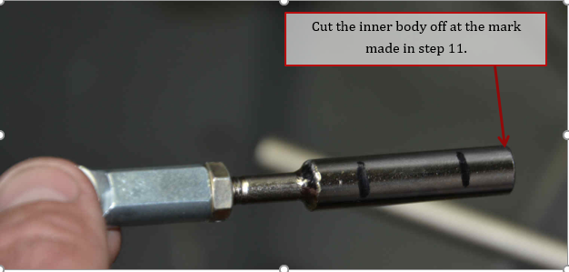
14. Remove both tail wheel parts from the aircraft. Cut off the inner body at the mark made in step 11.
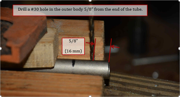
15. Remove forward spring and then drill a #30 hole 5/8” inches from the end of the outer body. A suggestion is to use a V-block clamped to the drill press table to keep the hole centered on the tube.
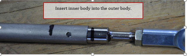
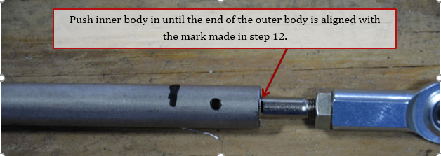
16. Insert inner body into the outer body until the line drawn on the inner body in step 12 is at the end of the outer body.
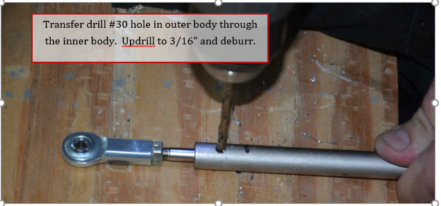
17. Hold the inner body in place and transfer drill the #30 hole in the outer body through the inner body. This can also be done on the drill press. Up drill to 3/16”, remove inner body and deburr.
Note: The inner and outer bodies have been nickel plated to prevent corrosion, avoid removing nickel plating while deburring.
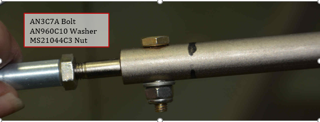
18. Reinstall forward spring and then inner body and then insert AN3C7A bolt, use a AN960C10 washer and MS21044C3 nut
19. The link can be installed permanently now if you wish, but it is recommended to leave it off until just before inspection. The airplane is easier to move around the hanger with the link removed as the tail wheel will free castor. With the link installed, you will have to apply more force to the tail to move the tail wheel past the locking detent to allow the tail wheel to swivel freely.