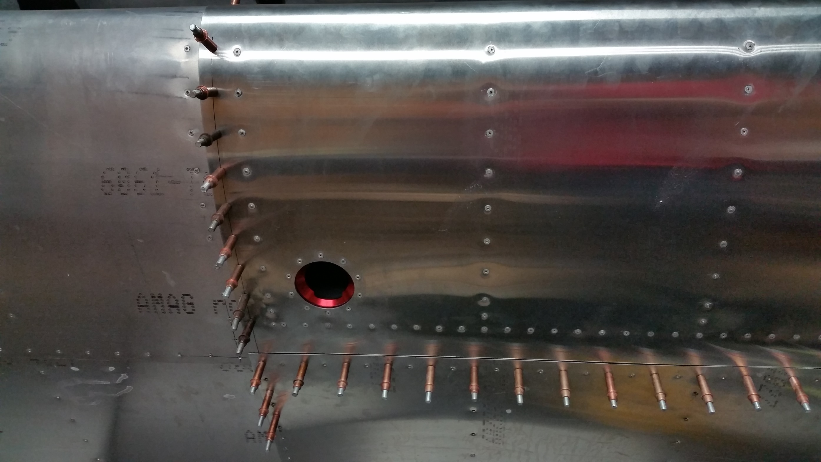
10. Carefully mark which holes in the aft skin you will be using for the fuel tank attach hardware (rivets or machine screw) See Plan sheet P-W-FT-attach for rivet /machine screw options layouts.
Note: Use extreme caution when laying out holes. The inboard holes will be very close to spar stiffeners, and have minimal edge distance!! See notes on Plan sheet P-W-FT-attach
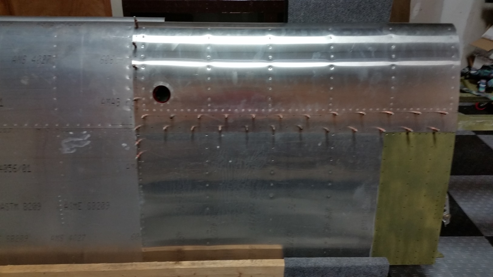
11. Verify FT placement, and drill through aft wing skins and cleco (this should be #40 at this point but if you already drilled skin to # 30 proceed with # 30) holes. Use Caution about what is behind/below what you are drilling (SPAR caps and stiffeners)
Note: Use extreme caution when laying out holes. The inboard holes will be very close to spar stiffeners, and have minimal edge distance!! See notes on Plan sheet P-W-FT-screw/rivet layout
12. Carefully lay out the forward row of FT attach hardware per plans sheet P-W-FT-screw/rivet layout noting cautions about holes proximity to spar stiffeners
13. Lay out the holes at outboard end of tank using plans sheet P-W-FT-screw/rivet layout as guide. And drill/cleco #40.

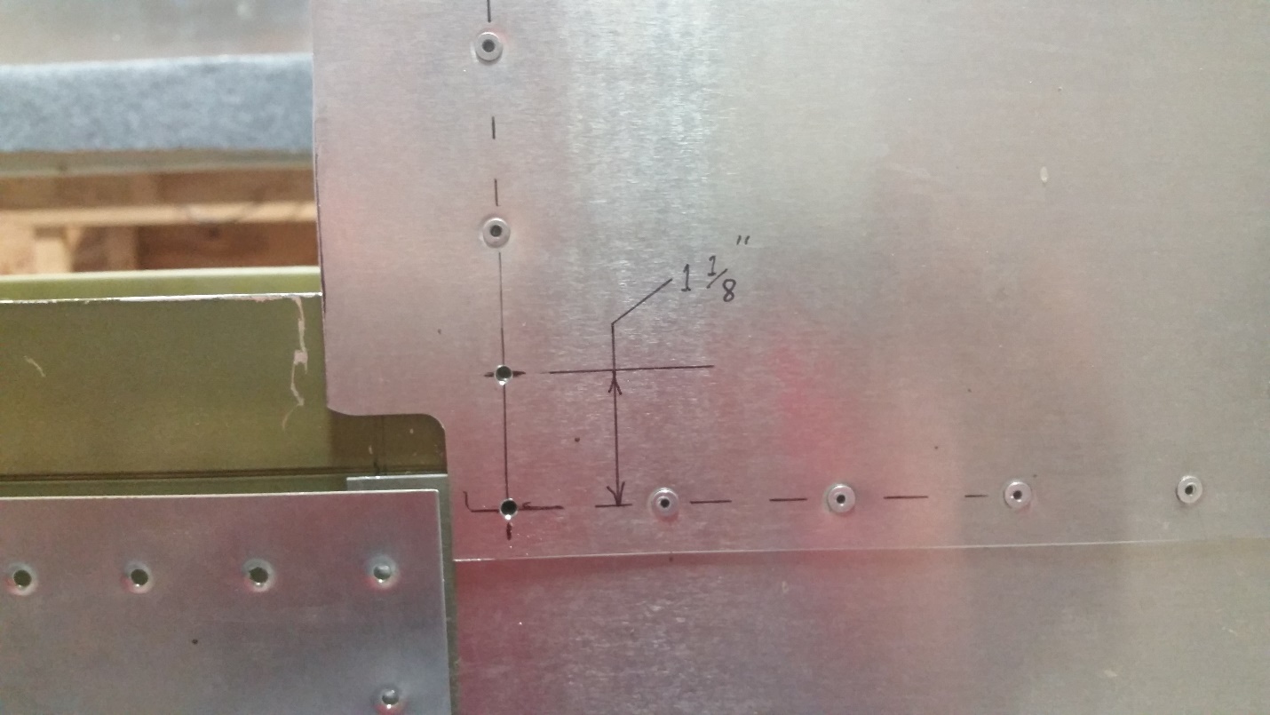
14. If not already accomplished layout and drill two holes at inboard end of leading edge skin at main spar, top and bottom (see photo)

15. If riveting the tank on drill all holes to #30 (if using DINQ dimple system deburr and dimple at #40)

If using machine screws drill appropriate size for the fasteners (flush or protruding MS screws/ nut plates)
16. Remove tank, deburr the tank skins and spar flanges
If using flush rivets dimple the wing skins and carefully machine counter sink spar flanges.
If using flush 6-32 machine screws carefully dimple skins and machine counter sink the spar flanges.
17. Repeat on second wing/ tank
18. Set the tanks aside and move forward with the build. See below.
Note: We recommend not permanently installing the tanks until much later in the build, after wing rigging and possibly painting.
