
Notes:
1.There are different sizes and shapes of wheel pants based on the size of the tire you chose. These steps are general in order to cover the variations. There is also variety of choices on how you want the wheel pants aligned and angled, so no dimensions are given here.
2.Wheel pants can get in the way and be damaged while finishing the aircraft; you will probably want to leave them off until after the inspection.
3.As with anything, it can take some time to get a good fit and finish with the wheel pants.
Installation Instructions
1. Raise aircraft wheels off the ground and place in a level condition. Be sure aircraft is stable and won’t tip over, this is especially important to watch if you have the engine installed.
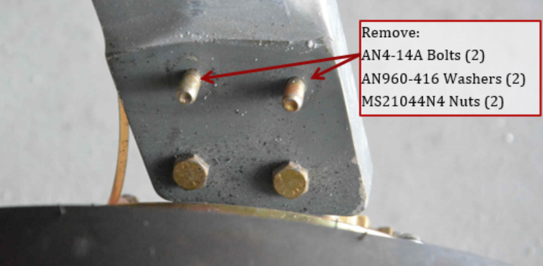
2. Remove the 2 upper AN4-14A bolts that attach the axle bracket to the landing gear leg.
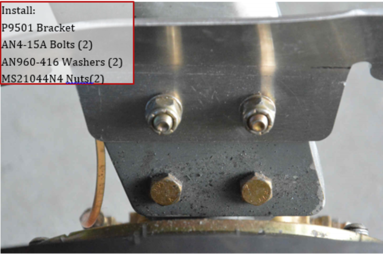
3. Install wheel pants bracket P9501 on landing gear leg as shown using AN4-15A bolts
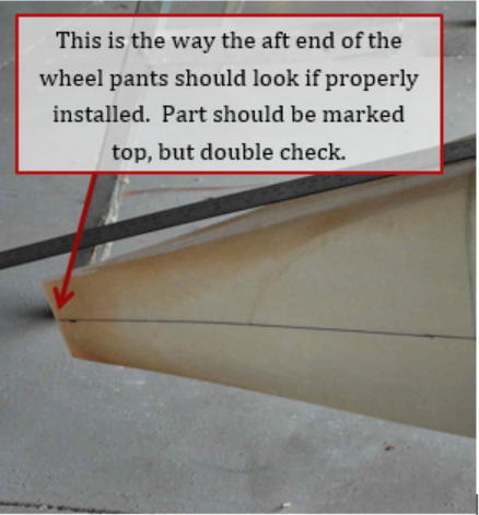
4. The top of the rear wheel pants should be marked, but you can tell by looking at the rear of the pant. The angle on the back should be oriented that the longest end should be on top, and angled forward on the bottom.
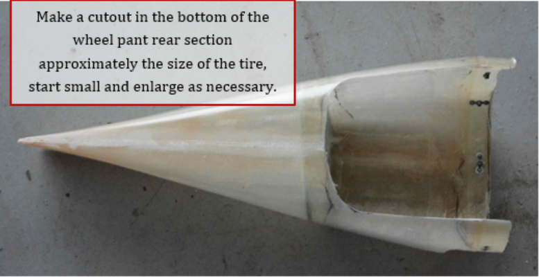
5. Make a cutout in the bottom of the wheel pants just larger than the tire in that area, do some test fits to see where tire is located. If you start small, you can increase the opening later as required.
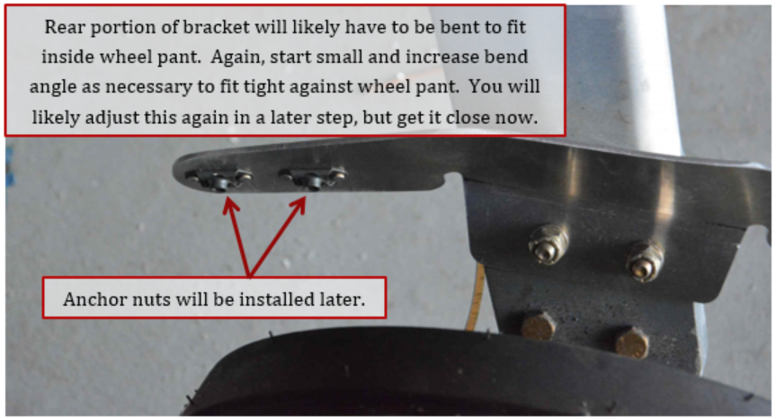
6. Rear arm of the bracket will most likely have to be bent to fit the angle of the wheel pants. There are different wheel pants depending on the size of tire that you are using. So, this angle will vary. Note the anchor nuts shown will be installed in a later step.
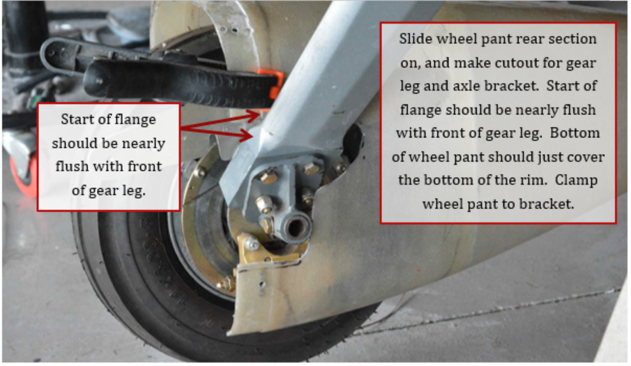
7. Slide wheel pants on bracket, verify that the wheel pant is high enough off the ground, preferably so that the rim is just barely covered. Mark for a cutout on the inboard side of the wheel pants for the landing gear leg and axle bracket. The start of the flange on the wheel pant should be approximately even the front of the landing gear leg. It is recommended to clamp the wheel pant to the bracket using a spring clamp or equivalent.
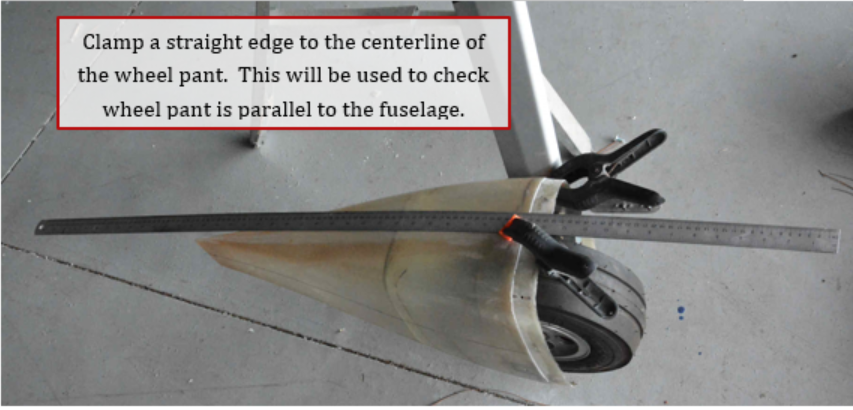
8. Clamp a straight edge to the top of the wheel pant down the center of the wheel pant. This will be used to measure that the wheel pant is parallel to the fuselage.
9. Draw a line on the wheel pant on outboard side in the center of the wheel pant. This line will be used to determine that the wheel pant is horizontal.
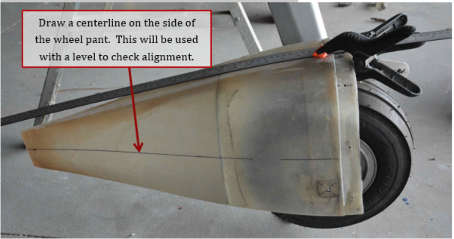
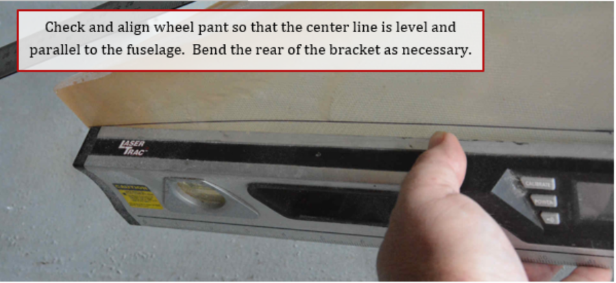
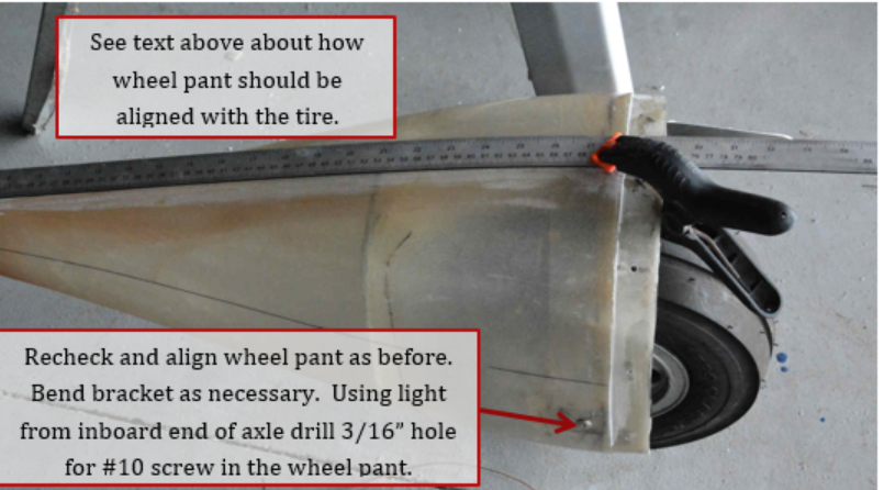
10. Remember, aircraft should be off the ground and in a level orientation. Use a level on the line drawn in previous step, adjust wheel pant until the line is level. Check that the wheel pant is parallel to the fuselage by measuring between fuselage and wheel pant. Plumb bobs can be hung from the fuselage to help. Remember the fuselage gets narrower ahead of the landing gear legs, so account for that difference (approximately 3/8” to ½” where I did my measurements). Bend the rear of the bracket as necessary to make sure wheel pant is parallel to the fuselage.
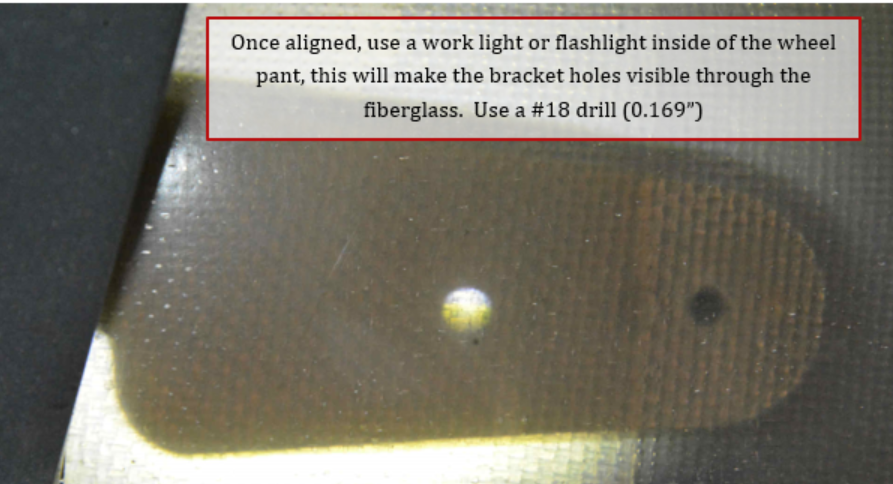
11. Once the wheel pant is aligned, with a small work light inside the wheel pant, you can clearly see the holes in the bracket through the fiberglass. Transfer drill these holes using a #18 (0.169”) drill bit.
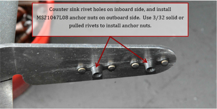
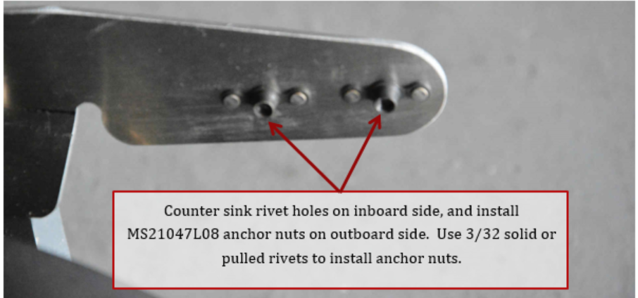
12. Remove the wheel pant. Countersink the inboard rivet holes for the anchor nut, and install MS21047L08 anchor nuts using either solid rivets or 3/32 pulled rivets.
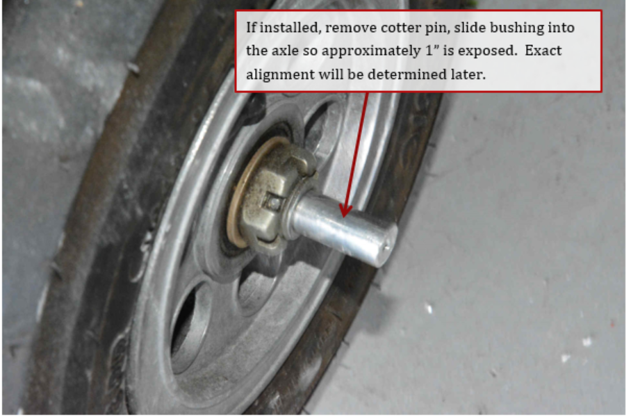
13. Slide axle bushing into place, if installed remove cotter pin from axle. Bushing will be free floating at this point.
14. Reinstall wheel pant using 2 #8 screws and reclamp straight edge on top.
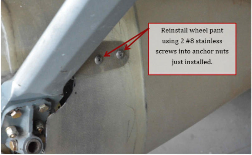
15. Check alignment of wheel pant in both horizontal and vertical directions. Adjust bracket as necessary. Also determine how you want the wheel pant to be aligned with the tire. You can make the side of the pant parallel to the tire, or possibly angle it slightly, so that the wheel pant is level inboard to outboard when sitting on the ground. The landing gear leg flexes, so this angle will be different between on the ground and in the air. Make sure axle bushing is touching the wheel pant side. After making sure pant is aligned use a hole transfer strap, or trace around perimeter of bushing on wheel pant and find the center. Transfer drill the hole in the bushing to the wheel pant using a 3/16” drill bit. This hole should be somewhere between 5/8” to 1” aft of the wheel pants flange depending on how you aligned the wheel pant.
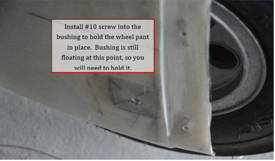
16. You can temporarily install a #10 screw through the wheel pant and into the bushing. The bushing will be drilled for the cotter pin later, at this point it is still floating.
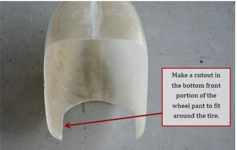
17. Make a cutout in the bottom of the front wheel pant, to match the cutout in the rear section. Again, start small and enlarge as necessary.
18. Fit front portion of wheel pant to the rear section. You will likely need to make a small cutout around the landing gear leg on the inboard side of the wheel pant.
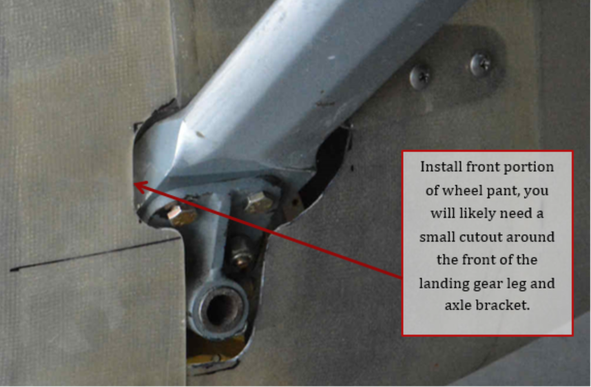
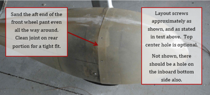
Note, the aft end of the front portion of the wheel pant may need to be sanded straight. You can also use a file on the flange of the rear portion to make a sharp clean joint line between the front and rear portions.
19. After the front portion fits the rear portion well, you can mark and drill #40 holes for a minimum of 5 screws. It is recommended to have 2 at the top corners, and 2 just up from the bottom of the wheel pant (1 on each side). On the outboard side of the wheel pant, place a hole in between the 2 just made. A recommendation is a a sixth hole (optional) at the top center in order to draw the 2 sections together tight. Cleco sections together as you go.
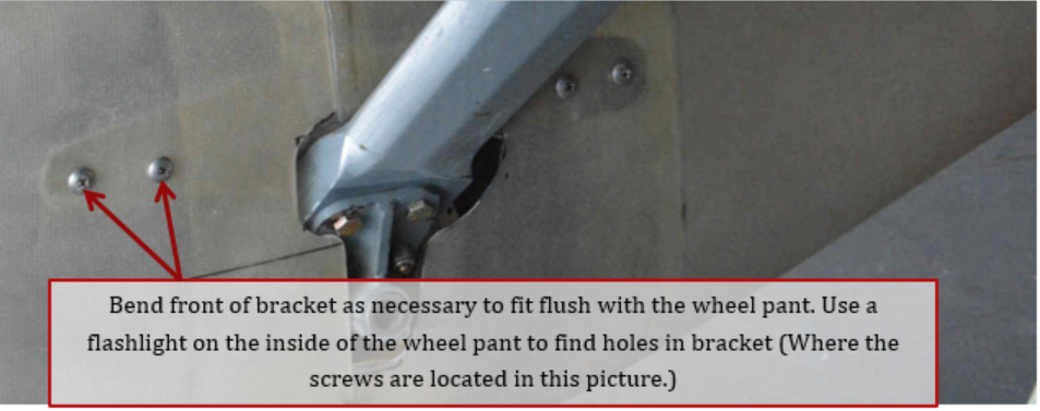
20. The front portion of the bracket may need to be bent slightly to fit tight against the wheel pant. Use a flashlight to locate holes in front section in the same manner as the rear.
21. Install anchor nuts on the front portion of the bracket.
22. Remove rear portion of wheel pant.
Optional - fiberglass a 0.063” thick piece of aluminum approximately 1 ½” square over the screw hole on the outboard side of the wheel pant.
Optional - add some fiberglass to the inside of the flange to make it thicker to allow for the counter sunk rivets of the anchor nuts. When cured, you can install #8 anchor nuts at each of the hole locations on the flange.
Optional - transfer drill hole for axle bushing screw through the aluminum plate.
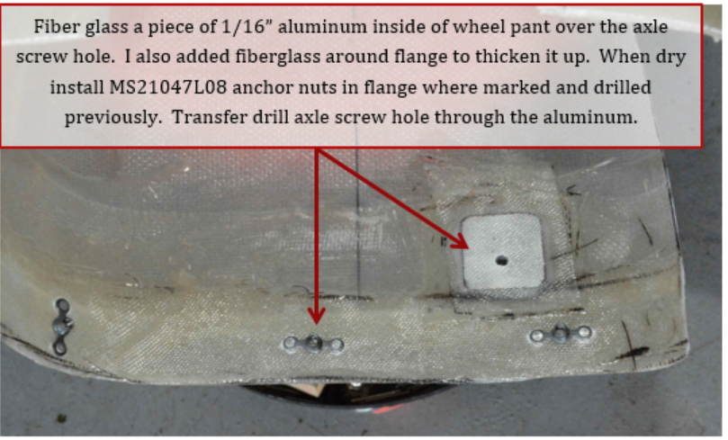
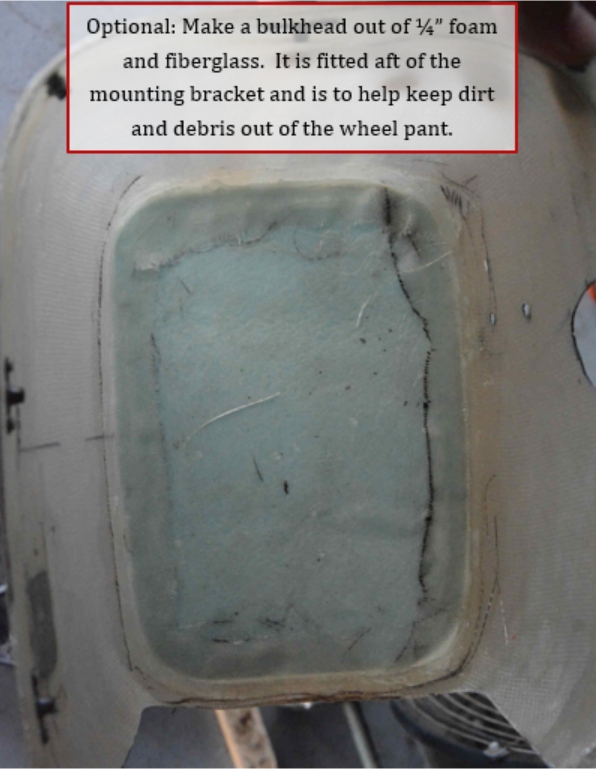
Optional - make a bulkhead out of ¼” foam with fiberglass on both sides, and fitt it into the rear section of the wheel pant. This is to help keep a large amount of dirt and grass from building up in the wheel pant.
Optional – glue it in place with some 10 minute gel epoxy, then later add a strip of glass cloth around the perimeter to seal the bulkhead to the wheel pant. Make sure bulkhead is aft of where the wheel pant bracket ends.
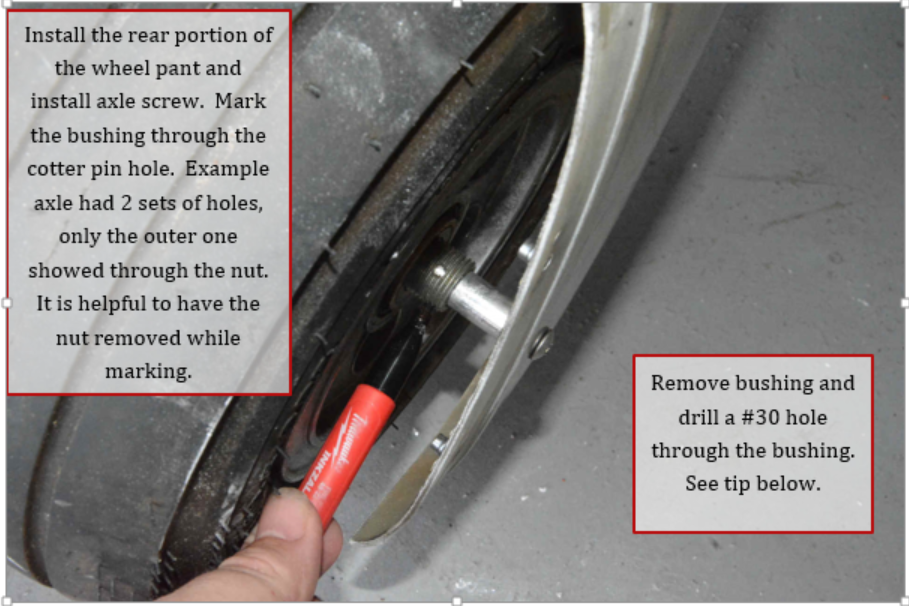
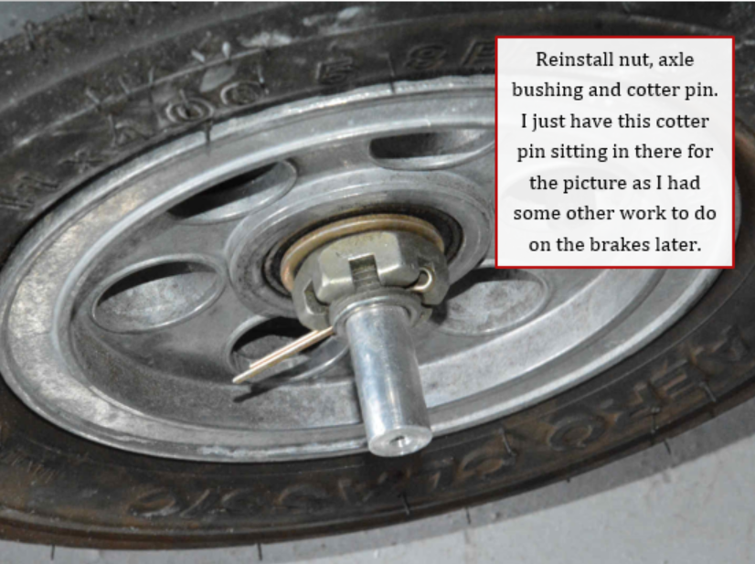
24. Reinstall rear portion of wheel pant on to the wheel. Install screw holding bushing to the outboard side of wheel pant. Mark the bushing using a pen through the cotter pin hole in the axle. This is easier with the wheel nut removed. Remove the rear section and the bushing, and drill #30 hole through the bushing at the mark.
Tip: if you are unsure about how well the hole in the bushing will align with the axle hole, you can drill through one side of the bushing only. Insert the bushing back into the axle, and hold in place with a cotter pin, then mark and drill from the other side. Make sure to run the drill bit all the way through the bushing.
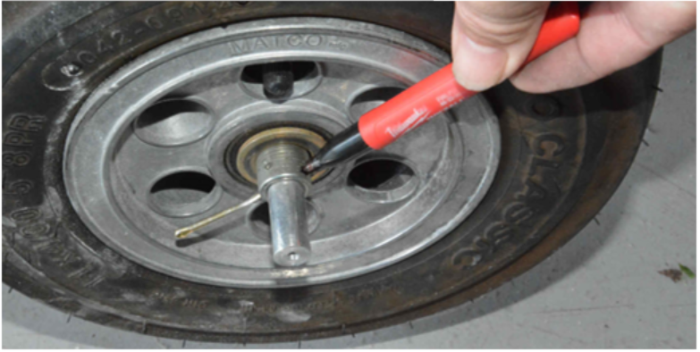
25. Install wheel nut and cotter pin per Matco specifications. Here the cotter pin is just sitting in the hole for this picture as we had other work to do on the brakes. You can install it permanently.
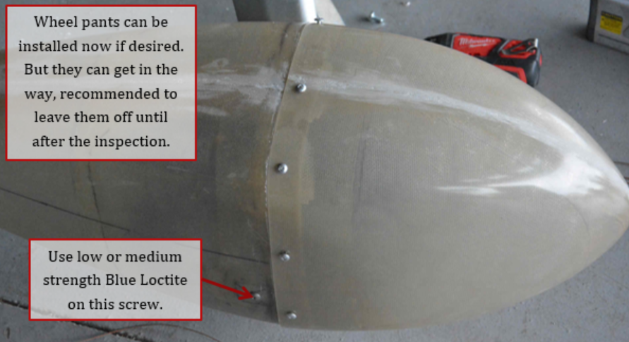
26. You can install the wheel pant now if desired or leave it off while painting and finishing. We use #8 stainless button head screws to hold the 2 portions together.
Note: The wheel pant can get in the way and be damaged as you are working on the plane. It is a good idea to leave off until after the inspection.
Note: Make sure the opening in the wheel pant is large enough to account for the flex of the side wall of the tire when landing.
27. Repeat for the other side.
