1. Extend the length of the slot in the bottom of the wing to the face of the rear spar. Be careful not to damage or scar the rear spar. Keep the same radius as how the slot was originally shaped.

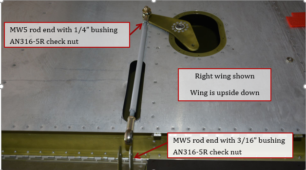
2. Press a 1/4” ID 5/16” OD bushing into MW5 rod end, and a 3/16” ID 5/16” OD bushing into another MW5 rod end. Thread AN316-5R thin check nuts and an MW5 onto the ends of the P2602 pushrod. One end should have a 3/16” bushing the other end a ¼” bushing. There are 2 P2602 assemblies needed.
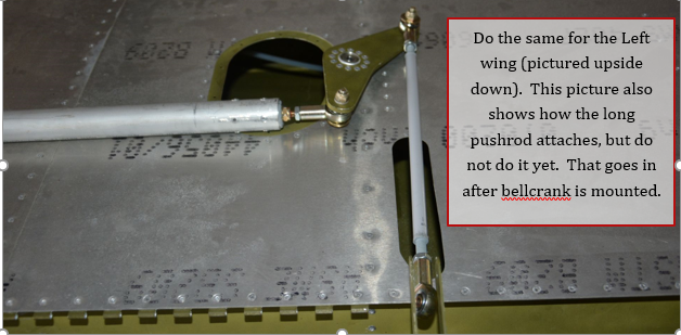
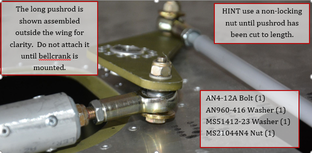
3. Attach P2602 aileron pushrod to the P2504 bellcrank using hardware shown below. The assembly is done outside of the wing then put into the wing through the oval access hole on the bottom of the wing.
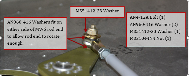
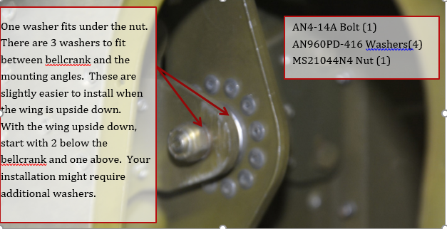
4. Slide pushrod and bellcrank assembly through access hole in bottom of the wing, feed the pushrod out the long narrow slot. The short pushrod is difficult to install inside the wing, so it is easier to install it as an assembly. The bellcrank should be shimmed using washers, such that there is no vertical movement of the bellcrank, and the mounting brackets and rib are not bent.
5. Insert the partially assembled long pushrod into the wing through rib 1. Attach to the bellcrank using the hardware called out below.
6. Install the aileron on the wing. Neutral position of the aileron can be found with a straightedge through the center of the tooling holes on the outboard rib, and center of the bolts for the counter balance arms on the ailerons.
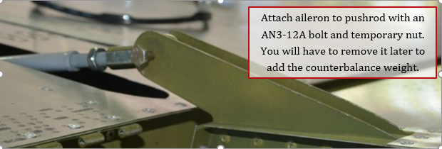
7. Attach the short pushrod to the aileron using an AN3-12A bolt and temporary nut.
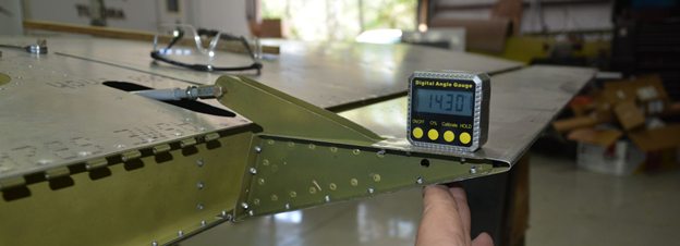
8. Check the maximum aileron throws. The ailerons have differential throws and should be able to deflect down 14 -15 degrees (without counterbalance weight) and up to about 25 degrees. Remember to zero the angle gauge at the neutral position.
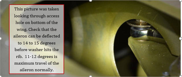
9. Check in the access hole that the short pushrod hardware stack up does not hit the rib until you have at least 14 degrees of travel. You can adjust the length of the short pushrod to get the minimum 14 degrees. Short pushrod can be shortened if necessary by cutting some threads off.
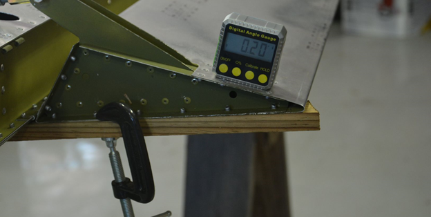
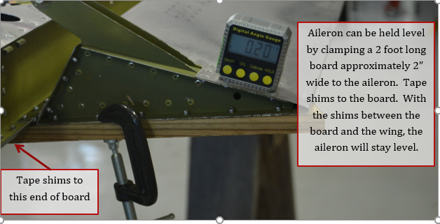
10. With the wing upside down, the aileron can be held in place by clamping a scrap piece of wood about 2 ft long and around 2 inches wide to the top surface of the aileron as shown below. Shims taped to the end of the board, between the board and the wing can be adjusted until the aileron is level per the pictures above.
11. Attach the joiner to the mount using a temporary AN4-13A bolt and nut. You will need a washer between the bearing and the mount. With the aileron level, make sure the joiner is parallel to the surface of rib 1. This can be done by measuring the distance between the joiner and rib 1 on both ends.
NOTE: The bearing on the joiner is incorrect in this picture and was only held on by clecos. We later changed the mounting of the bearing to what is shown in section 5.4.2.

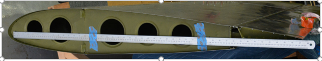
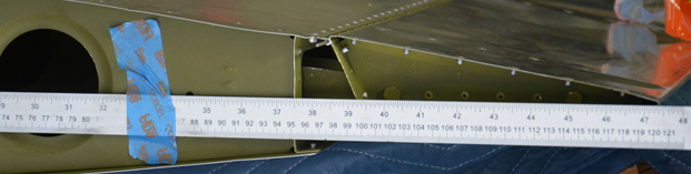
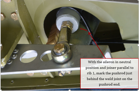
12. Temporarily attach the aileron pushrod end to the top of the aileron joiner. You can temporarily zip tie the pushrod end to the pushrod tube to help hold it in position. Mark the tube just behind the weld joint of the pushrod end. After it is marked, remove the pushrod end and aileron push tube, cut the tube to length.
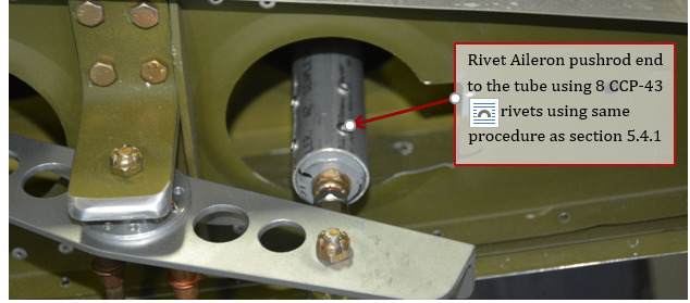
13. When marked and cut, rivet the pushrod end to the tube as done in section 5.4.1
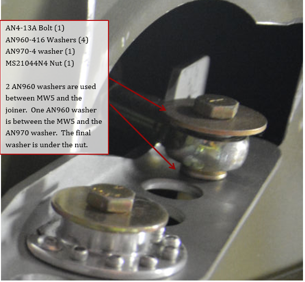
14. Pushrod end is attached using hardware below. A non-locking nut can be substituted until the pushrod has been cut to length.
15. With long pushrod installed, check maximum throws again. Verify that you can still get 14 degrees to nearly 25 degrees. That will ensure that you will have clearance at the minimum 11 degrees to 21 degrees of deflection required.
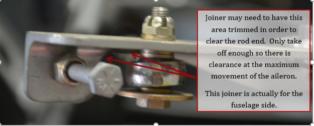
16. While checking aileron throws, check that the rod end does not rub on joiner. Joiner can be trimmed in areas shown, only take off the minimum necessary for clearance.
17. Repeat the above steps for the left wing.