
The spars are delivered to the builder assembled with screws in the proper order. It is important to mark the spars and note how they are assembled so you can get them back in the proper order after preparation. See plans for detailed layout and HERE for diagrams.
NOTE: The spar plates are reamed for pin bushings. Mark each plate before dis-assembling to ensure they stay together. The holes with the 8/32 screws from the factory have been reamed for proper fit of the fastener. Use these to keep the spar plates in alignment, see below.
1. Drill/ream all holes per plans
NOTE: Use caution and drill correct holes for fasteners. We suggest marking spar holes with several different colors. This way you can easily see what holes need which fasteners.
a.Example – red = don’t drill, blue for bolts, etc.
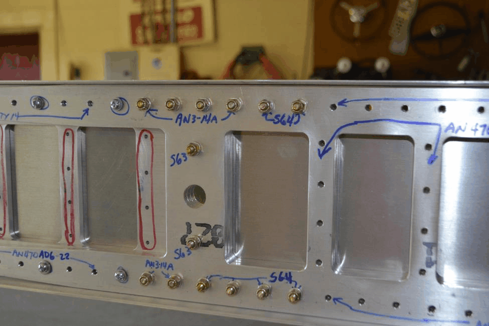
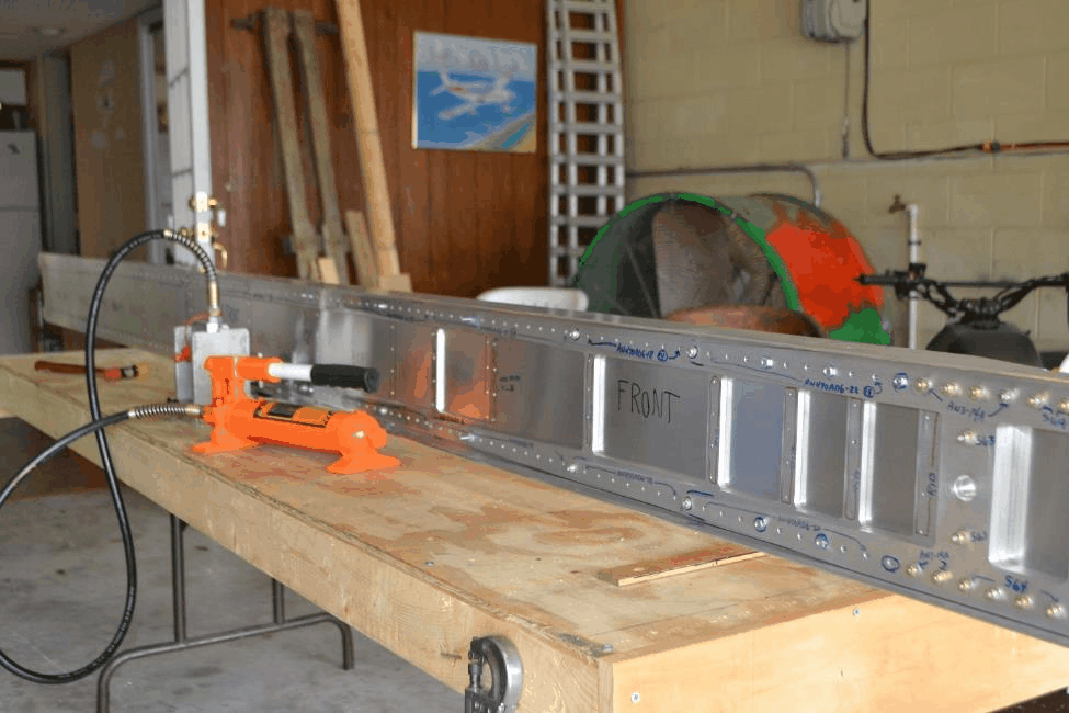
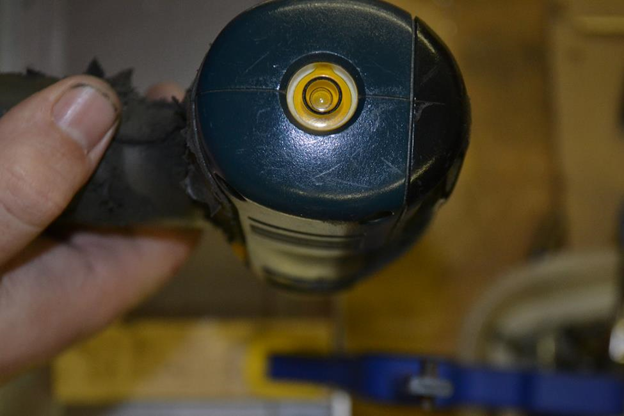
Photo of Buddy Henson’s Wing Spar – very nicely done! Clearly marked what goes where – leaves no question
With parts assembled in correct order (double check) verify the correct height and clamp/cleco together.
Plans builders use dimensions on plans and locate/cleco the outer web to the caps with the 1/8” holes at wing rib locations. Leaving the clecos here will help prevent you from up drilling. Then mate to the inner web and stiffener assembly using plans as guide. At all times ensure spar height, and straightness.
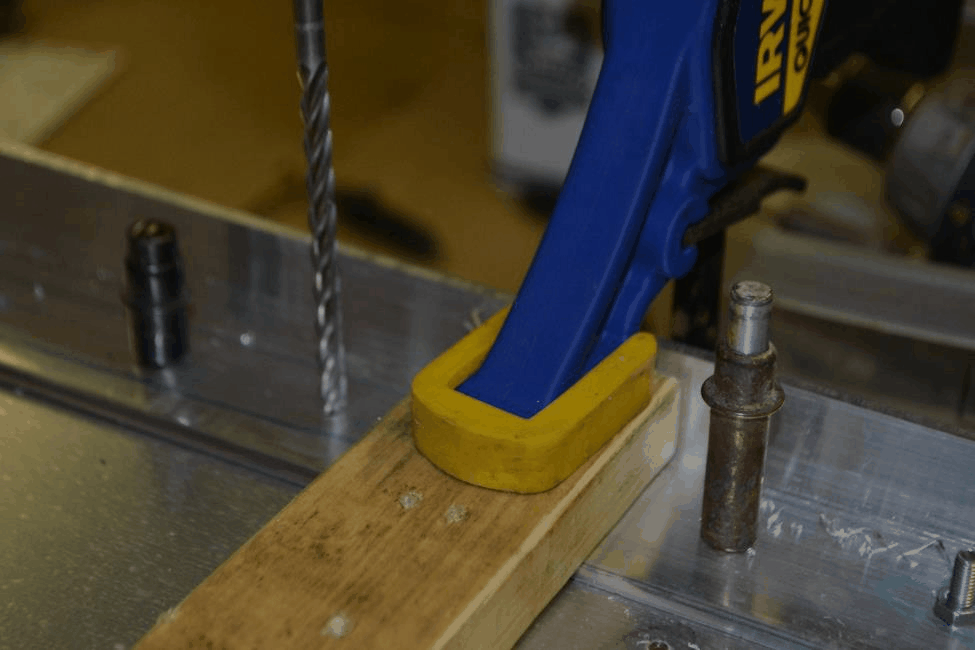
NOTE: When drilling spar “stack” use a clamp near the drilling area to ensure the “stack” is “tight”.
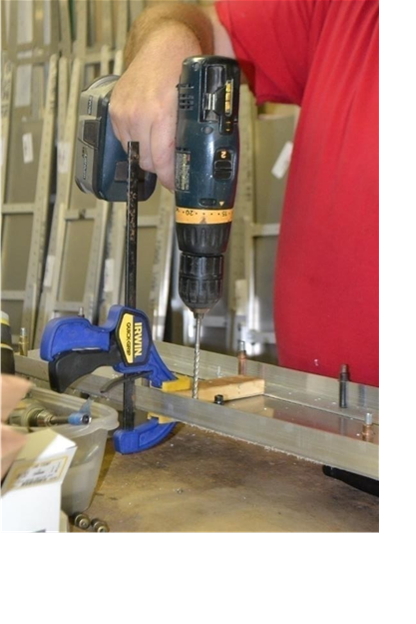
Drill all holes marked for the 3/16” rivets to #10 and cleco as needed. Use care when drilling through the thick sections. A small drill press on your work table maybe helpful. We have also had success using a 3/8” variable drill with a bubble level in the aft end to ensure the drill is vertical when drilling.
A drill block may be also be helpful in drilling good holes. This can be made by drilling a # 10 hole in a piece of Aluminum bar stock (see plans and Photos for an example).
The first 40 kits or so used AN3 bolts which have a tolerance of 0.004” and required measuring the bolt and drilling and reaming to match the bolt. Typically a 3/16” or 0.1875” reamer. Later kits use NAS6603 bolts that are tight tolerance bolts with only 0.001” tolerance. For these bolts, we recommend drilling with a #16 (0.177”) then use a 0.1890” reamer.
We suggest some test holes in scrap and trial fit of bolt/screw to perfect your bit size/procedure. “Tight fit” in this case means the bolts will need to be very lightly tapped into the hole with a light hammer. Take your time and get these correct.
Note: The 3 holes with 10/32” screws near wing bushing have been reamed at factory to ensure alignment. Use caution when dissembling and be sure to mark each part so they go back in exact order.
2.Countersink as required (see plans for locations of countersunk holes)
NOTE - Countersinking is only required on the spar cap flanges in the center section, and where the MS24694-S63 or NAS7403-13 screws are located by the wing pin holes.
3. Dis-assemble, debur and complete final part preparation.
Disassemble and debur, countersink for flush fasteners, and ensure proper finish on all surfaces. The wing spar parts come CNC machined. The edges must be polished to remove any tool marks. You should also polish any scratches etc. The spars are the most heavily loaded structure in the aircraft so take your time and ensure a smooth finish on all parts. We use a belt sander with a fine belt to polish outside edges. A small flap wheel and drum sander can be used on inside areas. Use care when handling spar parts to prevent scratches, etc. Remember the spar is the backbone of the wings - scratches, nicks etc are stress risers. To ensure a long fatigue life take the time needed to achieve good surface finishes.
4.Prep parts for primer if desired. Use a very thin coat of primer only.
5.Re-assemble and install bolts/then rivets
Starting with the above mentioned 3 holes that had 10/32 screw in them install the correct fasteners called on plans. Clamp the spar “stack” tightly while tapping the correct fastener in the holes. Install with AN 365 nuts or MS21042L3 nuts and washers as needed. Installing these 3 bolts first will ensure wing pin bushing fit.
Next install all bolts and screws using orientation on plans sheets.
NOTE - The bolts at wing rib locations (dashed circle on plans offset to outboard of 1/8 vertical row of holes in web) are not installed at this time.
NOTE - It is suggested to install hardware store 10-32 screws and nuts temporarily in the holes reamed for wing rib bolts. This will help hold the stack together especially in the thicker sections where clecos will not go through the entire stack, and they will help to prevent accidently installing rivets in those holes. Also, clecos can interfere with the operation of the squeezer when installing rivets adjacent to the cleco.
Install 3/16” rivets per plans. SPA has a specialty built rivet squeezer available that makes setting rivets quick and easy with little chance of damaging spars or rivets. If you do encounter a poor rivet install, it is likely best to leave it alone rather than attempt to drill the rivet out. Drilling the large rivet out in a thick stack is very difficult to do without damaging spar parts!
6.Installing pin bushings
To install the wing pins bushings we use a 3/8” or a 7/16” fine thread bolts and nut as a “puller”. Make sure you use the aluminum spacer washer (see plans) under shoulder of bushing. We use some grease on outer side of the bushing to prevent galling of aluminum. A large “1/2” drive socket can be used on back side to allow the bushing to fully protrude the spar. (see photos)
