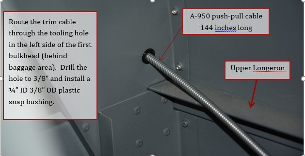
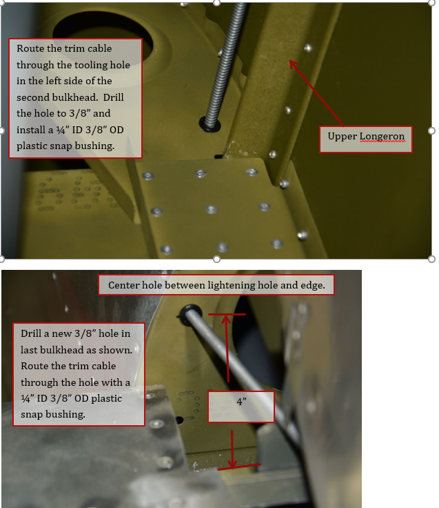
1. With the belly skin removed from the tail cone, route the elevator trim cable through plastic snap bushings installed in each of the 3 bulkheads of the turtleback area. The cable is Aircraft Spruce p/n 05-169144 A-950 push-pull cable 144 inches long.
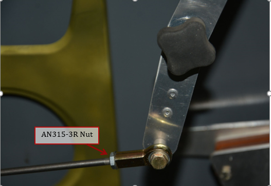
2. If not previously installed, screw the trim cable into the MW3 rodend.
3. Push trim lever as far forward to just aft of the steel fuselage tube. Hold the clamp to the control cable and against the left map pocket. Clamp or hold it in position. The control cable should be at its shortest length, and should be parallel to the rudder cable. Move lever aft to just in front of the map pocket while holding clamp and verify that the cable operates smoothly.
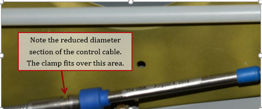
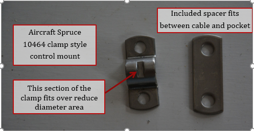
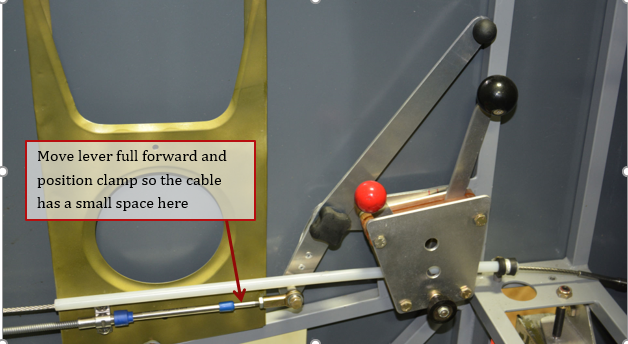
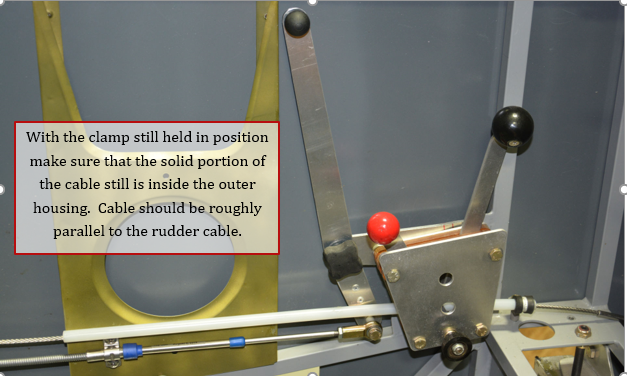
4. Drill 2 #18 (0.169) hole through clamp into map pocket. Attach clamp with the spacer between the cable and the pocket using 2 MS35206-245 screws.
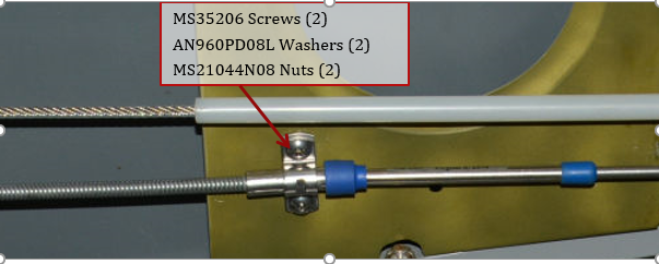
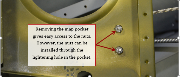
5. Pull the control cable taut and place clamp around control cable and hold against the rudder cable tunnel in the baggage compartment. Drill through the hole of the clamp into the tunnel bottom. Attach clamp with a screw and nut. The belly skin of the tailcone was removed for access while installing the trim cables.
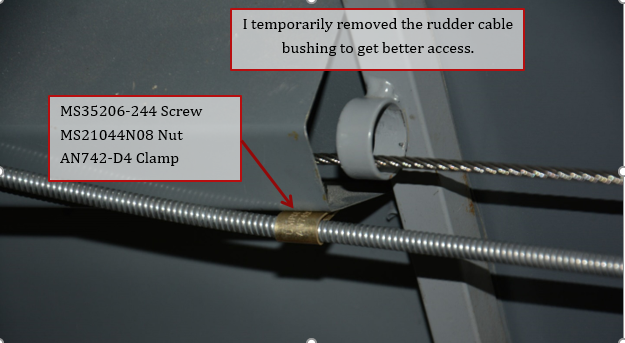
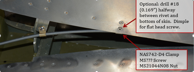
6. Mark on the centerline of the forward vertical stabilizer spar flange that protrudes below the vertical stabilizer skin. Drill a #18 hole.
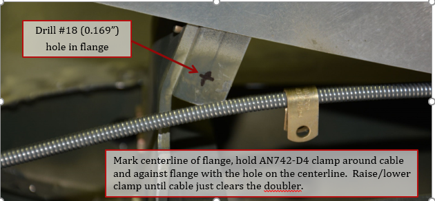
7. Pull control cable taut in tail cone. Install clamp with a MS35206-244 screw and MS21044N08 nuts.
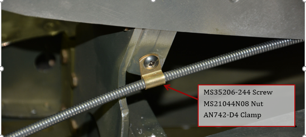
8. Optional: For aircraft using the counterbalance weight, this clamp can be used to prevent the weight from hitting the cable. The skin should be dimpled for a flat head screw so it doesn’t interfere with the tail fairing.
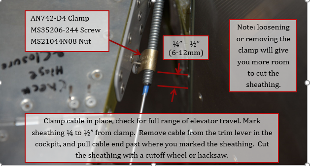
9. On elevator, install AN742-D4 clamp with the loop side up. Verify the elevator still moves freely through its full range of travel. Mark the outer sheathing about ¼” to ½” past end of the clamp. Take the cable end loose from the trim lever in the cockpit, and pull the cable past where you marked the sheathing. Loosening the clamp gives more room to cut the sheathing. Cut the sheathing with a cutoff wheel on a Dremel tool or hacksaw. Push cable back and reattach to the trim lever.
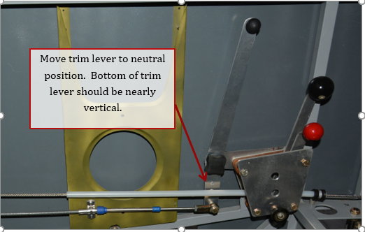
10. Move trim lever to the neutral position, approximately ½ way through its range of motion. Bottom of trim lever should be nearly vertical.
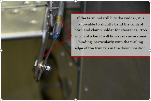
11. Place the trim tab in the neutral position. Attach control cable to elevator trim tab using a 05-16100 bolt type terminal available from Aircraft Spruce. Discard the nut and one of the washers.

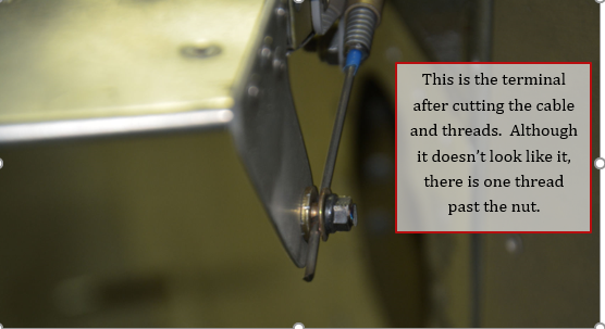
12. Check rudder travel and elevator trim travel and verify the rudder does not hit the terminal of the elevator trim. If the terminal still hits, it is acceptable to bend the trim control horn slightly for clearance. However, bending it too much can cause a bind.
