
Note: before starting HT/VT install see plans sheet P-T-HT/VT install, and verify/complete the trimming of parts and skins. Some or all trims may have been already completed.
Note: the goal during HT/VT install is to have the HT parallel with the top of instrument panel cross tube, and “square” with the fuse centerline when viewed from top. Trim aft and fwd HT mount angle if not factory trimmed (P-T-HT/VT install prep) and the procedure below carefully so the proper angle of incidence will be set.
1.Fuselage should be level in both axis, same as previous section on joining the fuselage halves.
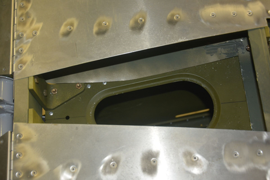
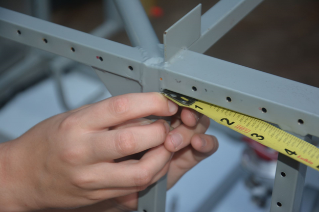
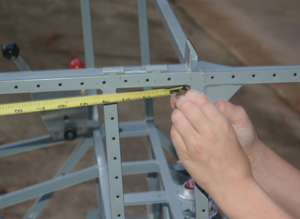
2.Position aft mounts on fuselage 0.032” forward of aft edge of deck. The mounts should be positioned per Plans sheet P-HT/VT-install
3.The skins of early horizontal stabilizers need to be cut as shown in drawing (P-T-HT, VT install). Mark and drill holes in the Horizontal stabilizer spars as shown in the same drawing.
4.On early Horizontal stabilizers, you need to mark and drill #30 pilot holes on forward spar per drawing (P-T-HT, VT Install).
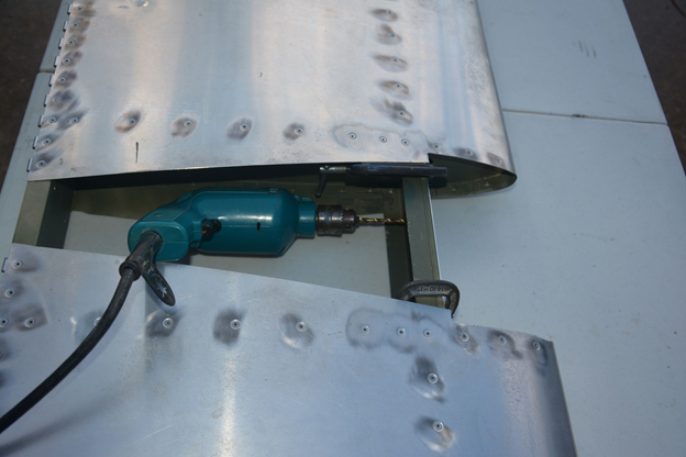
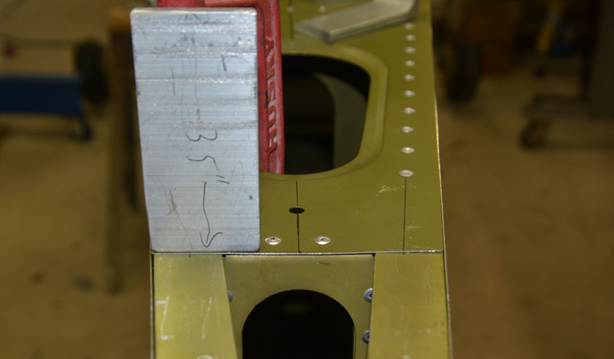
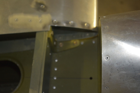
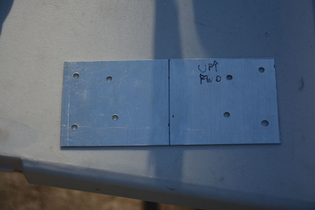
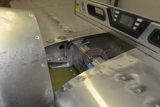
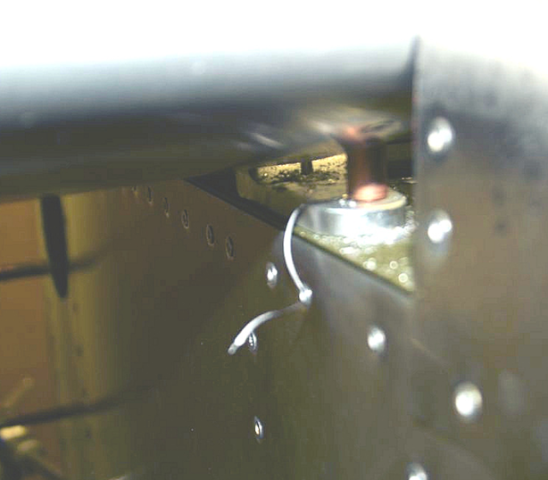
5.If you don’t have a right angle drill for drilling the Vertical stabilizer (look ahead at the vertical stabilizer install), you can make a drill template for later use. See picture below, and the picture above, which has 1/16” thick aluminum plate mounted of the front of the forward spar.
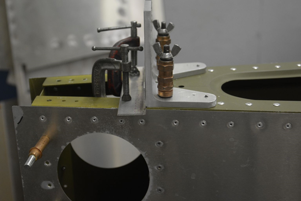
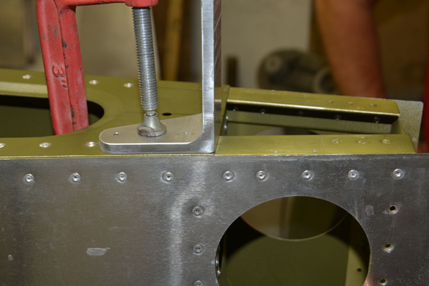
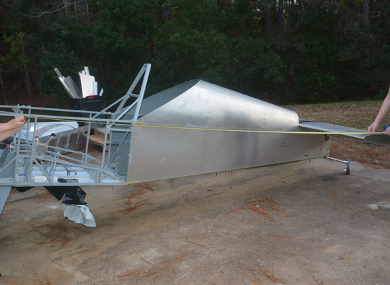
6.Set horizontal stabilizer on aft deck of the fuselage. Top of the aft spar channel should be flush with the top of the aft mount angles. Center the horizontal stabilizer using the center line on the aft spar with the center line on the aft deck.
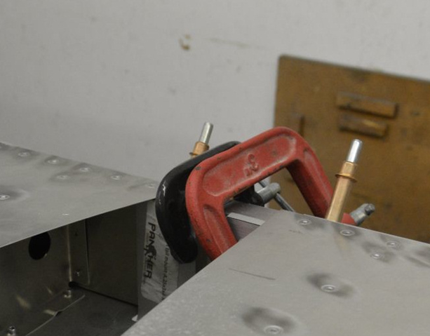
7.Clamp the forward mounts to the forward spar. Top of the forward stiffener should be flush with the tops of the forward mounts. Adjust the position of the mounts by reclaiming until the stabilizer is level. All mounts should be sitting flat on the aft deck.
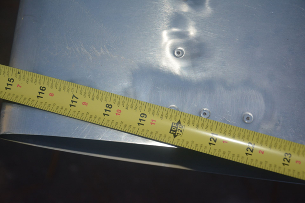
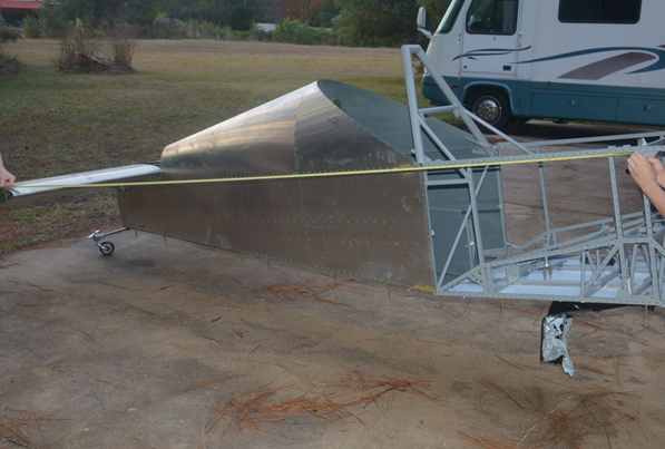
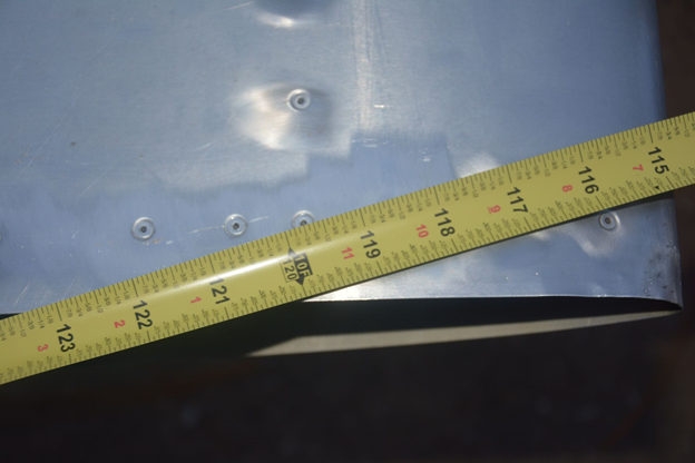
8.Measure from outboard most spar rivet on each end of the horizontal stabilizer to a point on the forward fuselage. Measurements from both sides should be as close to the same as you can make them. Less than a 1/4” difference is preferred. Recheck the level, and position of the mounts from the edge of the upper longerons. Check if the horizontal stabilizer is still centered. Make any adjustments necessary, and repeat steps 6-8 until everything is correct.
9.
10.
