
1. The roll servo is located under the seat and connects to the control stick via a pushrod. The bolt on the control stick is replaced with a longer bolt. There is a mount that needs to be made, it is essentially the same as the GRT provided mount, but taller and the mounting flanges point in to give more room for mounting the servo.
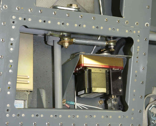
2. The autopilot pdf file contains full size patterns for all the items needed for the autopilot installation. Make sure the file is printed full size, the roll servo mount almost completely fills an 8.5” x 11” page. You can find the PDF template using this link: https://flywithspa.com/documentation/panther/servomountmodel.pdf
3. Make the pushrod from a 2.75” piece of 6061-T6 round stock ½” diameter. Drill and tap one end for ¼-28 threads, and the other for 10-32 threads. Thread an MM-4 rod bearing and AN315-4R check nut into one end of the pushrod. Thread an MM-3 rod bearing and AN315-3R check nut into the other.
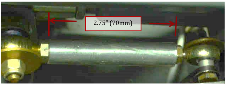
4. Remove existing bolt from control stick that connects the aileron pushrods. Replace it with an AN4-21A bolt. Attach the pushrod assembly as shown. There is an AN960-416 washer between the MM-4 rod end and the AN970-416 washer.
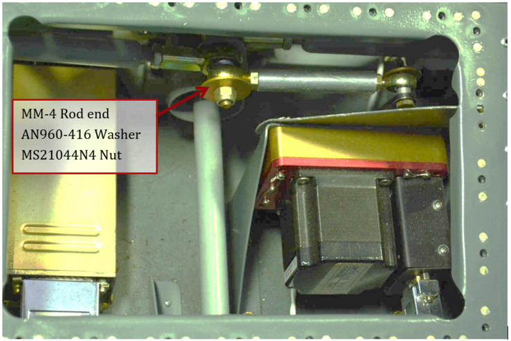
5. Temporarily install roll servo into mount using AN3H-4A bolts. There is a roll brace bracket that bolts into the top 2 holes of the servo.
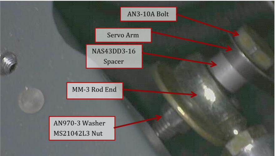
6. Attach the pushrod to the outermost hole on the servo using an AN3-10A bolt, NAS43DD3-16 (1/4” spacer), AN970-3 washer, MS21042L3 Nut.
7. Servo should be pushed against the stiffener on the cockpit floor under the right side of the seat. The brace bracket should be touching the upper seat frame. Move servo forward or aft until the AP pushrod is parallel to the starboard aileron pushrod. Verify the control stick can be moved through its entire range without it hitting anything. Mark location of the servo mounting.
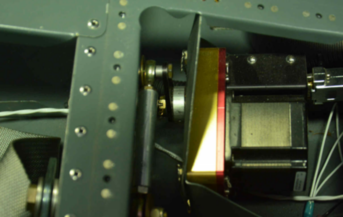
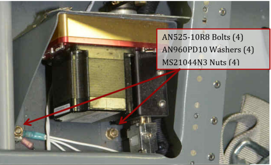
8. Remove the servo and transfer drill the mounting holes of the servo bracket into the floor and the stiffener. Attach mount to the floor with 4 AN525-10R8 bolts, MS21044N3 nuts, AN960PD10 washers. Attach mount to the stiffener with 2 MS35206-245 screws, MS21044N08 nuts, AN960PD8 washers.
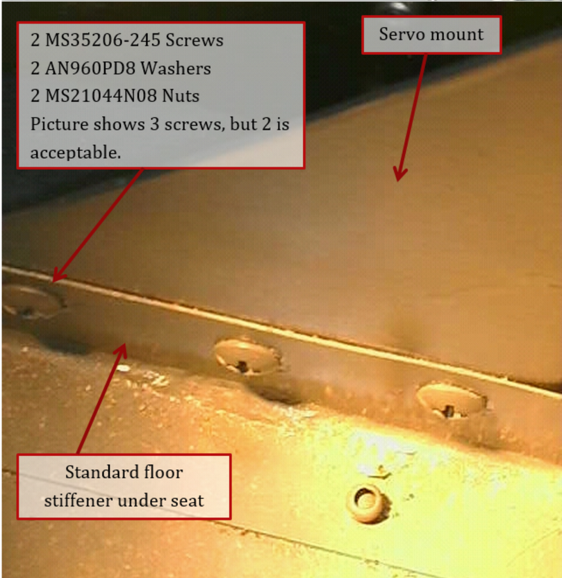
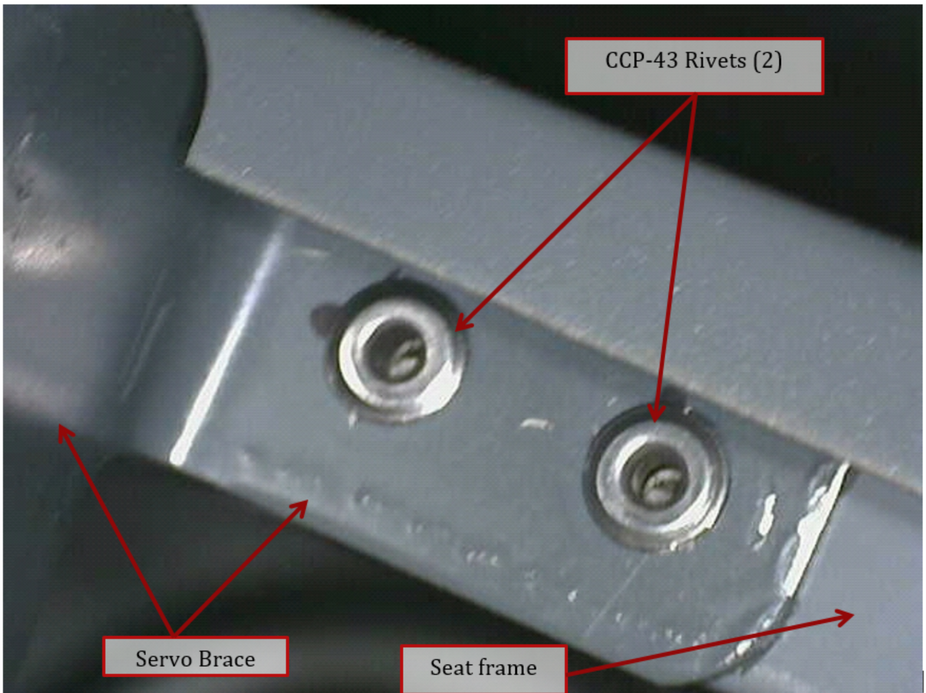
9. Temporarily attach the brace to the upper 2 holes of the mount and check alignment of the tab to the seat frame. Trim the brace tab to match angle and size of the seat frame. Drill 2 #40 holes through tab and into the frame. Up drill to #30, deburr and install 2 CCP-43 rivets.
10. Reinstall servo, verify all the hardware. Safety wire the heads of the bolts.
NOTE: The pushrod should be adjusted so the servo arm points straight up when the stick is centered.
