
The P-W-FT-inner ribs contain the mounts for the fuel level sending unit and the fuel pick
up.
1. Using plans and photos as a guide install (cleco) the P-W-FT –inner support and the
P-W-FT pick up doubler. The Pickup doubler provides extra stiffness to mount the
fuel line quick disconnect to. It also serves as a stabilizer for the P-W-FT fuel pick up
tube. (Note: your P-W-FT-inner support may have an erroneous ¼ inch hole near
the aft tooling hole, in the inner rib. These holes will not line up and will be sealed
off by sealer in a later step, see photos.)
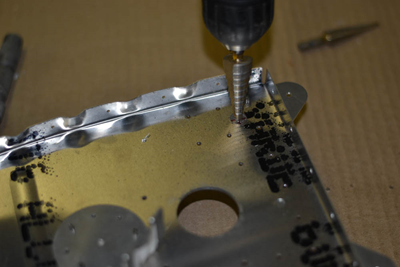
2. Using a “stepped” drill bit (Uni-Bit) Drill the 7/16 hole for the AN833-4D bulkhead
fitting for the vent system and test fit.
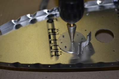
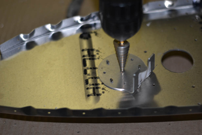
3. Using a “stepped” drill bit (Uni-Bit) Drill the 9/16” through the Pick up doubler for
the AN833-6D bulkhead fitting as shown
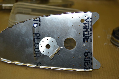
4. Prepare the P-W-FT-fuel pick up tube per plans. Use a high quality flaring tool. It should be bent so slots are down and that is will almost touch tank bottom. Use caution and don’t not “kink “the tube. Tighten the AN818-6D nut so the “flats “will align with slot in the P-W-FT-pick up doubler.
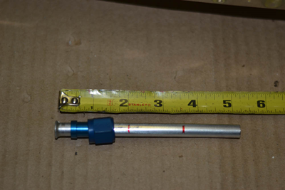
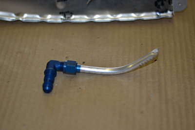
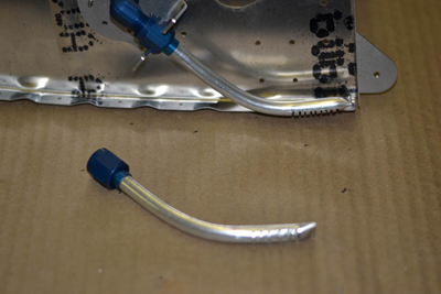
5. Test fit the P-W-FT fuel pick up tube and adjust the bends on the P-W-FT-pick up doubler so it captures the “flats” on the AN818-6D nut. You can spread or close the “finger” slightly and adjust bend angle so the they fully engage the nut
6. Fit the fuel sending units (P3701, P3702) per photos. The commercial part numbers are Stewart Warner IEF35B (right) and IEF35C (left).
Be sure to note the orientation of the units carefully. It should angle downward. You can check with an ohm meter to verify its correct function. With the float arm down (low fuel) you should read high resistance (around 250 ohms) with the arm up (full fuel) you will read low resistance (about 30 ohms))
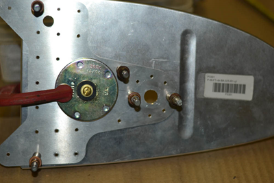
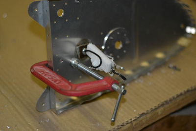
7. Drill the 5 mounting holes to 5/32”, and fit the K1000-8 Two Lug Anchor nut (MS21047L08) as shown. It is important that the anchor nut attach holes extend through to the outside of the inner support. This allows them to be drilled out and changed in the future if ever needed.
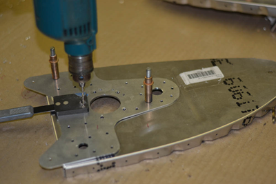
8. Drill the inner support attach rivets per plans to #30
9. Disassemble the inner rib, debur all holes. Counter sink the nut plate rivet holes on outside of inner support.
10. Install a ¼ “ soft rivet in the forward tooling hole (see plans and photos) these rivets can be set by placing the “factory head against on the top of a vise or hard (metal) surface and tapping the back side several times with a medium size hammer. You do not need to use a rivet set. These only serve as a plug for the tooling hole. They will be sealed later.
11. Install ¼” soft rivets into both tooling holes of rib 6 at this time (or rib 5 if building 10.5 gal tanks) these will be sealed later.
12. Reinstall the inner support with clecos
