
See plans (sheet P-W-FT-fixture) and make Qty 2 P-W-FT-fixtures out of ¾ MDF (or plywood).
•The plans sheet can be spray glued onto the wood and used a template for cutting.
•The saddles need to be made accurately and identical.
•The saddles are designed to rest on a level table top, and be able to rotate to any of the 3 sides and still be aligned so the tank doesn’t have a twist. To do this the saddles must have the outer edges the same. We recommend staking them and block sanding the edges.
•We suggest you network with other builders as someone near you may already have these. You can also purchase the “saddles” CNC routed from SPA.
• Use blue tape where skin will sit to prevent scratches.
• Precisely mark the “aft skin line” per plans on each saddle.
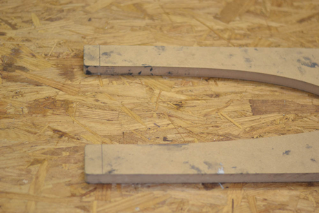
Join the two saddles per photos and plans with a “2 x 4” 34 inches long use one long wood screw in each end so they are rigid end to end but can rotate as needed to remain level on a flat surface.
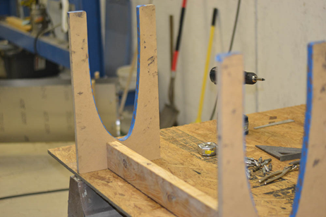
1.On a level table top with the tank fixture nose down slide in the r P-W-FT skin R. Some small bags of sand (or anything heavy but soft or padded. the aileron counter weights wrapped in a small towel or foam work well, but see cautions on working with lead in aileron section) as weights can help the skin stay in saddles.
2.Note : if matched tool ribs cleco all ribs in place per layout shown on plans (sheet P-W-FT- general layout)and proceed to step 9 this section
With tank skins fully into saddles align the aft end of the skins with the previously marked “aft skin lines”. These lines are for reference, if needed you can adjust the skins slightly above or below line, but be sure the skin edge is the same distance from the line at all 4 places. When fitted properly, clamp in place using 4 “C” clamps, and some scraps of wood to protect the skins. (See photos)
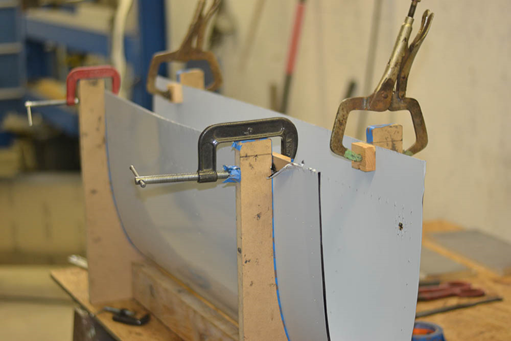
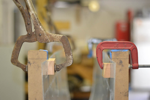
3. At each rib location mark a line 3/8” forward of the centerline of the aft row of rivet holes along the aft top and bottom of the skin (see photos).
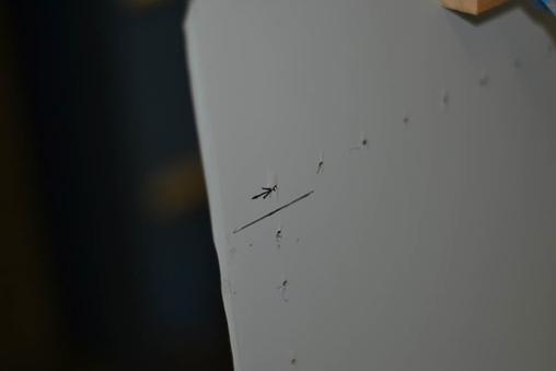
4. Slide in the P-W-FT inner rib. With it fully inserted into the skin the aft rib flange should be flush with the line drawn in step 3. When satisfied with position and ensuring ribs centerline is centered on skin holes, drill and cleco #40 the aft hole on top and bottom and again verify the above noted position
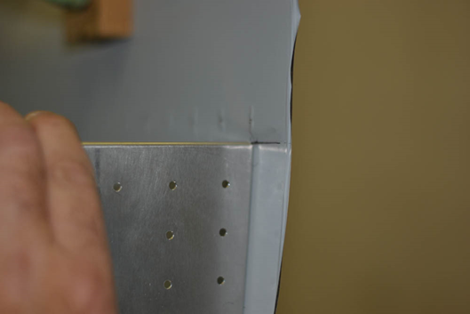
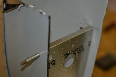
5. Continue alternately top and bottom and working forward drilling and cleco-ing while maintaining the “centerline”. When drilling the “nose” of the rib use gentle pressure to avoid the “tab” from pushing away from drill.
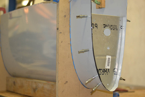
6. Repeat these steps on P-W-FT-rib 6 R
7. Fit ribs P-W-FT-ribs 2-5 R. Verify the aft rib flange is at the line drawn in step 3 and on the centerline of rib flange. Skip down to third hole from aft on top and bottom and drill/cleco#40.
8. Continue alternately top and bottom and working forward drill and cleco while maintaining the “centerline”.
9. Fit P-W-FT-tank back in place and cleco into aft rib flanges
10. Drill the remaining (aft two) holes in ribs 2-5 top and bottom.
(Note: match hole kits skip to here) cleco tank back in place
11. Drill #40 and cleco through skin and into tank back. Start at each rib location top and bottom then in between each rib. Then drill all holes.
12. Up drill all rib /skin holes #30
Note: If using flush skin rivets and the Cleveland DINQ dimple process do not up drill any exposed skin rivets
13. Remove P-W-FT tank back
