
Introduction
Note: SeeJoggle Strip Angle if you have not yet installed these
The Panther cowling and spinner is a crucial part of making the "boxy" sheet metal airframe have a streamlined attractive appearance. SPA can provide several different cowls for various supported engines. Other engines like the Jabiru 3300 have cowl systems provided by the engine supplier. By design the cowl length for the Corvair, Lycoming, Continental and Franklin are the same length. These engines span an installed weight from 260-335 lbs (fully installed including cowl, propeller, spinner, oil cooler, exhaust system , and oil etc). The heavier engines are moved aft and typically use a propeller spacer to achieve the same prop flange location. The Corvair has a specific cowl. The other "traditional" aircraft engines all utilize the "universal " cowl.
The UL line of engines, (350 and 520 ) are lighter and span from approx 225lbs-295lbs fully installed. These engines are moved further forward and use a different propeller flange length to help optimize the CG location. The UL engines also have a specific cowling.
Below is a table of dimensions for the propeller extension lengths for the various engines. We have put much effort in determining the following information, but many variables such as engine mount bushing length, and bolt torque effect the exact distance.
The design "nominal' distance from the cowl face to firewall at center line is 31 5/8 inch's. The cowl will still fit well between 31 1/2- 31 31 3/4 inches . If you move further forward you will not have enough material to trim of aft end of cowl for good fit to flange strips. If you move the cowl further aft the shape will not be correct around the aft perimeter of cowl and excessive body work will result for good appearance.
We suggest mounting the engine with proper bushings and fully torquing the bolts. Then accurately measuring the distance from the firewall to the prop flange. Subtract this dimension from 32 5/8 and this should provide the exact spacer length you need. You can compare to the "design"spacer length below.
*Note: When using the Vans 13 inch spinner we place the cowl face 1 inch behind the prop extension face. This will give approximately 1/4 inch clearance from the installed spinner back to the cowl face. This is a "livable' distance , and clearance for installing and removing the cowl system without constantly damaging the paint.
We suggest making a cowl alignment fixture per Drawing P-F-cowl alignment fixture for the appropriate propeller flange on your engine. This will make positioning the cowl correctly much easier.
Link to the Cowl Alignment Drawing.
Below we show a Corvair cowl being installed but the process is the same for any of the cowls.
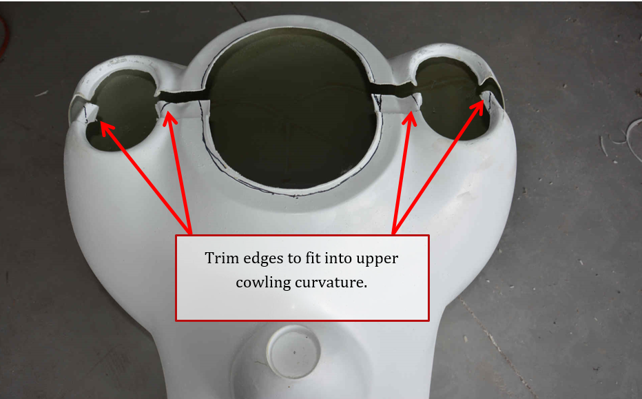
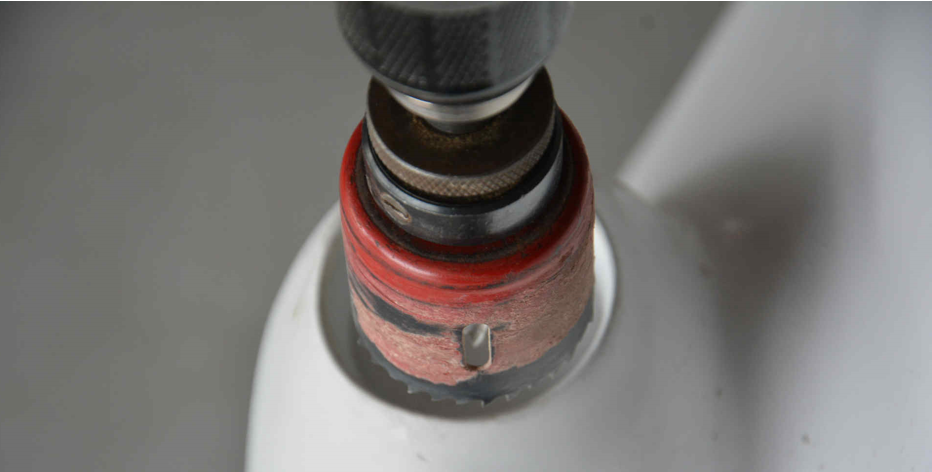
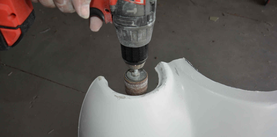
Cut the excess material from the openings in the cowling. A hole saw works well for the smaller holes, and then can be cleaned up with a drum sander in a drill. Trim the center opening to the edge of the flat section as marked below. Because the lower cowl has flanges that fits inside the upper cowling around the openings, it can cause the cowl sections not to fit together properly. Tapering the flanges on the lower cowl around the cooling air inlets enough for the halves to fit together helps.
 \
\
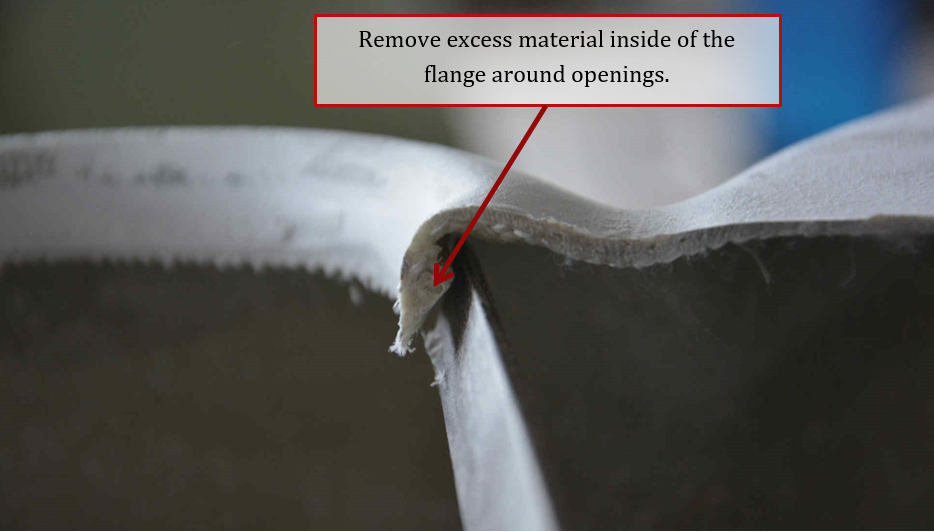
Remove the excess material inside the flanges on the upper cowl. A file works well for this.
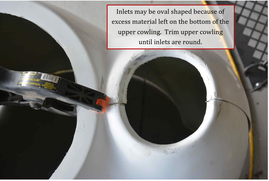
The upper cowl has excess material at the bottom to allow for variations in mounting. If you fit the upper and lower cowlings together, you may see that the air inlets are oval shaped instead of round. Measure the height vs width of the inlets, and remove that amount from the bottom of the upper cowl section. But only remove it around the front section. The rest of the top cowl will be trimmed after mounting on the aircraft.
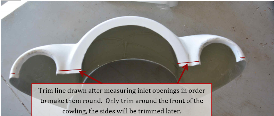
You can see the line that we trimmed to below. Again only trim the upper cowl around the front, leave the rest long until you fit to the aircraft. Keep working on the front until you get even openings and good looking joints between the upper and lower portions of the cowl.
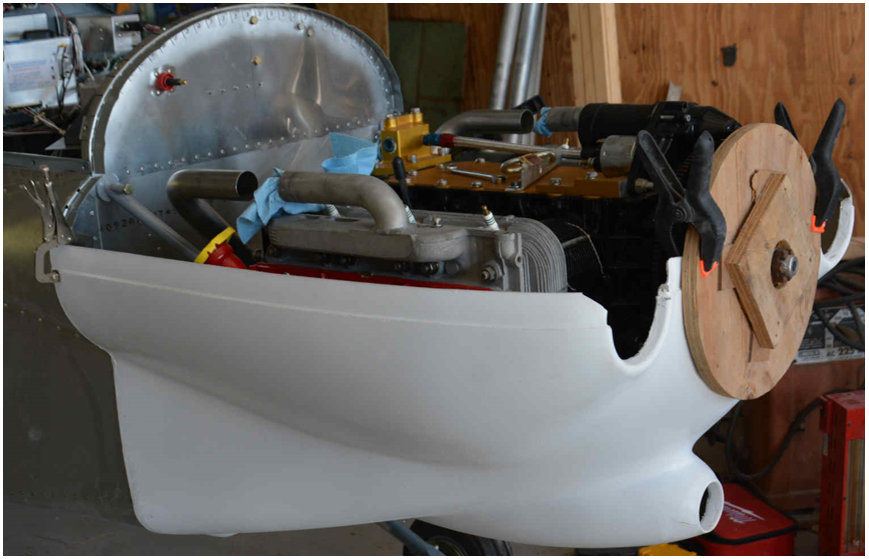
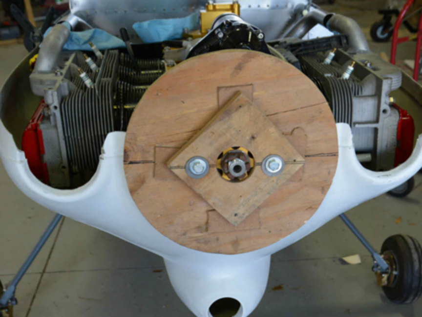
With your engine installed and the bolts torqued properly we set the fixture on the crank shaft and temporarily clamped the lower cowling in place to give a quick check of how it fits.
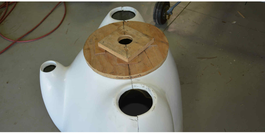
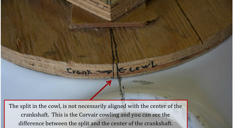
The split on the cowl is not necessarily on the centerline of the crankshaft. Draw a line through the center of the crankshaft opening of the fixture. With the cowl halves together, place the fixture on the front and move the fixture until it is centered on the opening of the cowling. Mark the fixture where the cowl split is.
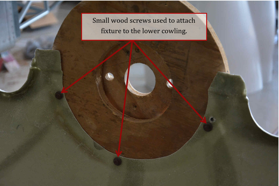
Use some short screws through the flange on the lower cowl and into the fixture. This will hold the front of the lower cowl in the right place. Holes from screws can be filled later if desired.
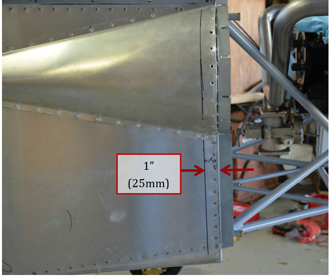
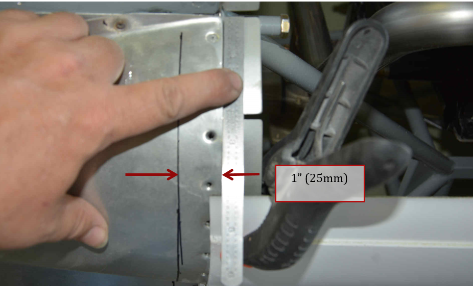
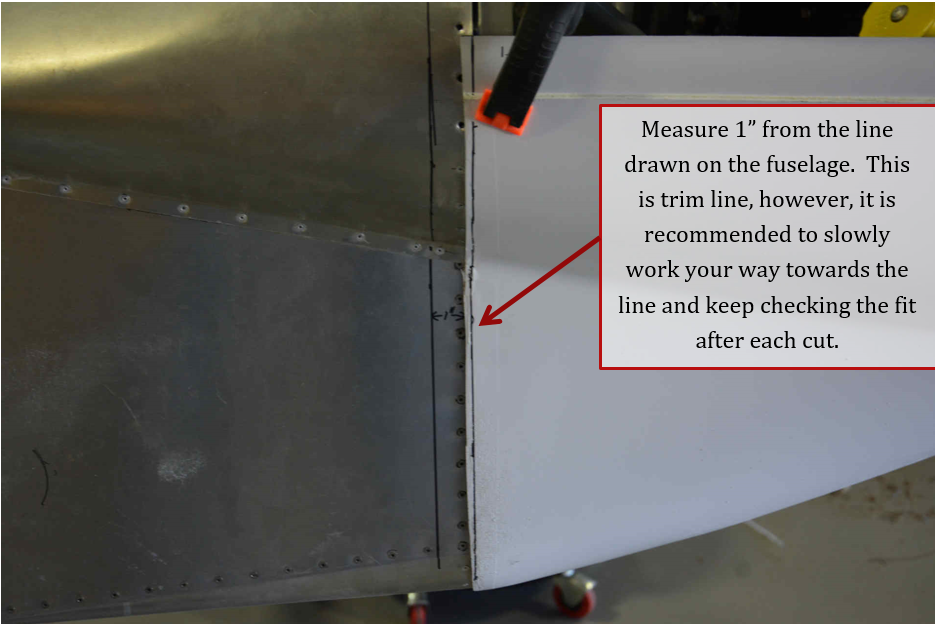
On the aircraft, draw a line 1 inch from the front of the side skins on both sides. This will be a reference line to mark the cowling from, so be accurate making this line.
We bolted the fixture to the engine, this helps keep the fit consistent, but does take longer to remove the cowling, which will have to be done several times.
Clamp the cowling in place at the firewall. Make sure the cowling fits well with the exhaust tunnel fairings on the bottom and the lower cheek line. Adjust cowling until you have a good fit.
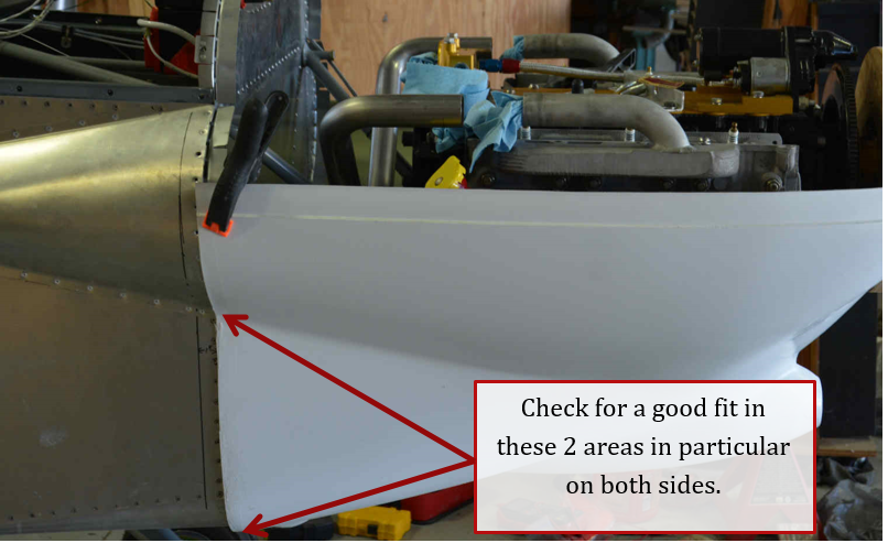
Draw a line on the cowling 1” away from the reference line drawn previously. This will be your trim line for the cowling.
CAUTION, do not cut on the line right away, leave some excess material and slowly work your way back to get a good tight fit to the fuselage. This can take some time, and you will have to remove the lower cowling many times.
NOTE: The engine mount has some offset thrust designed into it, so one side of the cowl may be slightly longer than the other.
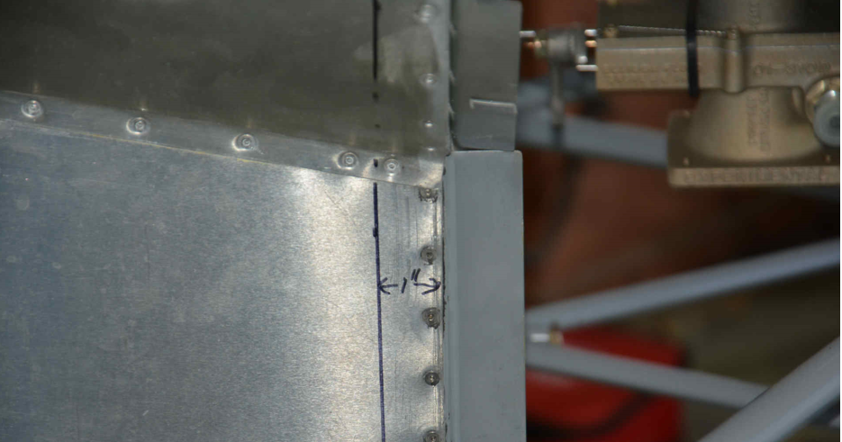
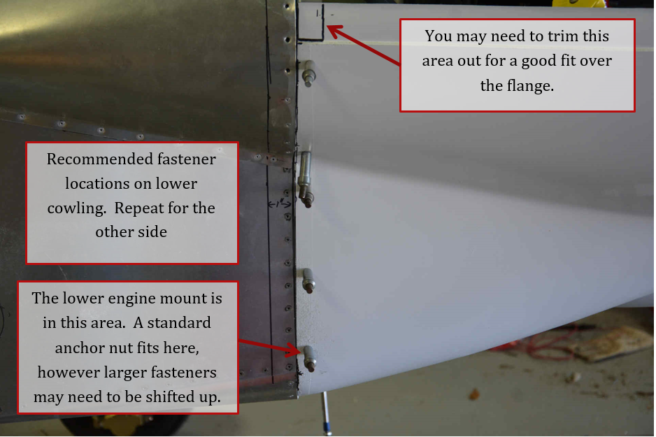
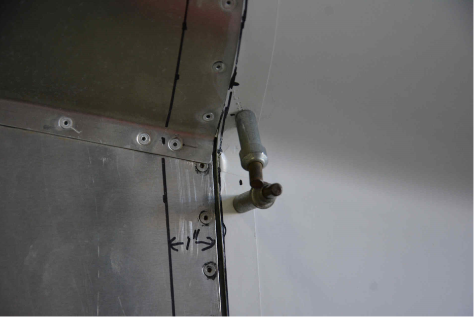
After you have the lower cowl fit properly, you can drill holes for mounting. It is recommended to have one hole in the center of the flange tab just below the split line. You will need one hole above the cheek line and one below the cheek line. Also locate one hole towards the bottom of the flange strip, and the final hole should be centered between the other 2. That is a total of 5 holes per side. The exact location of the holes will be determined by the type of anchor nut/ fasteners used on the cowling. You need to keep proper edge distance on the mounting flange for the anchor nut rivets. The lower cowling is not removed very often, so we choose to use anchor nuts and stainless steel screws for it, but Camlocs or Skybolt quarter turn fasteners could be used also.
NOTE: the fit of the cowling to the airframe is also dependent on the flange that was mounted around the cheeks and the upper firewall. If the cowling is not flush with the edge of the skin, you can add some strips of fiberglass inside the cowling as shims until you get a proper fit. You may also need to trim and sand at the upper rear corner for the flange to fit properly. Again, this depends on how your flanges are mounted.
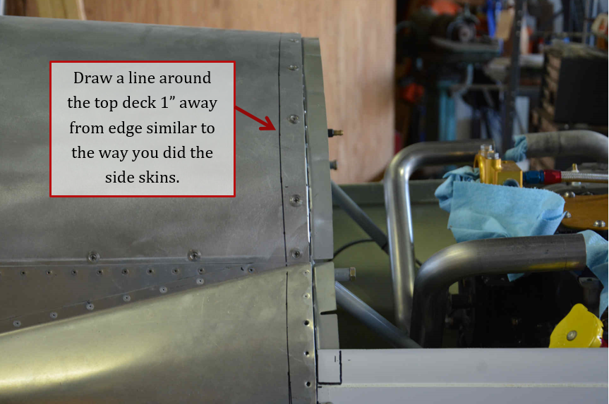
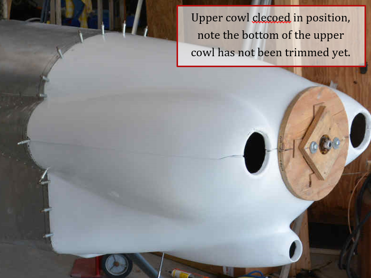
Make sure you have a line around the front deck skin 1” back from the front edge, same as you did for the lower cowling.
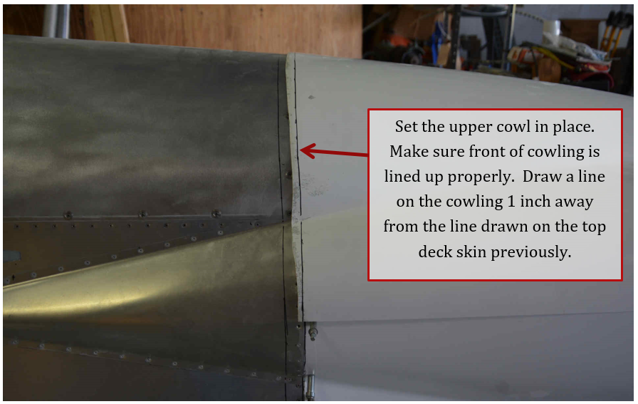
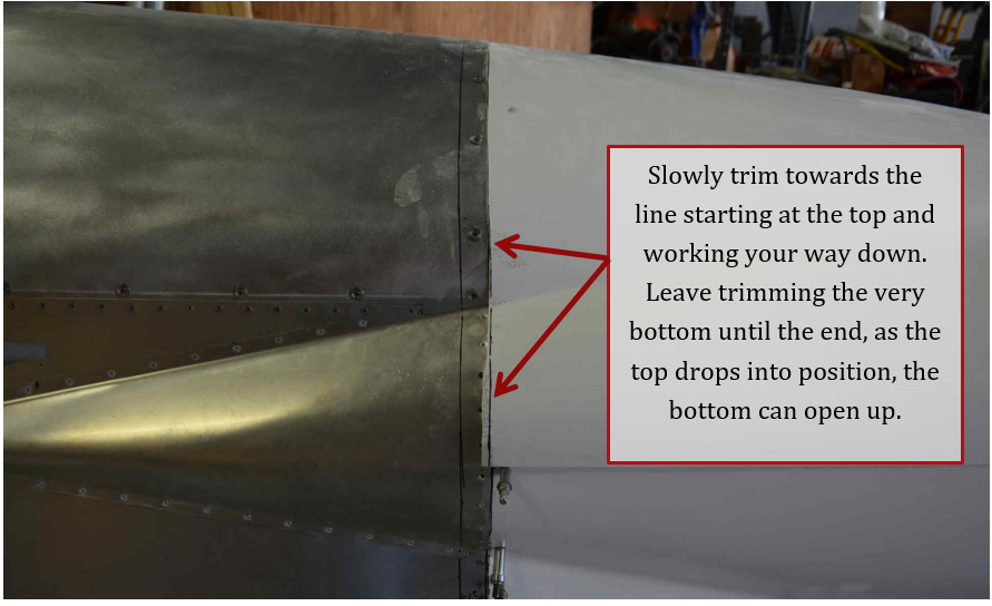
Place the upper cowling in position. Make sure the front is fitting well with the lower cowling. Draw a line on the upper cowling 1” from the line on the skin same as the lower cowling. Again slowly trim the upper cowling back. Start working around the top center front deck skin. Leave the cheek areas long initially. Because, as the upper cowling drops into position after trimming, your joint at the bottom could open up, so trim it last.
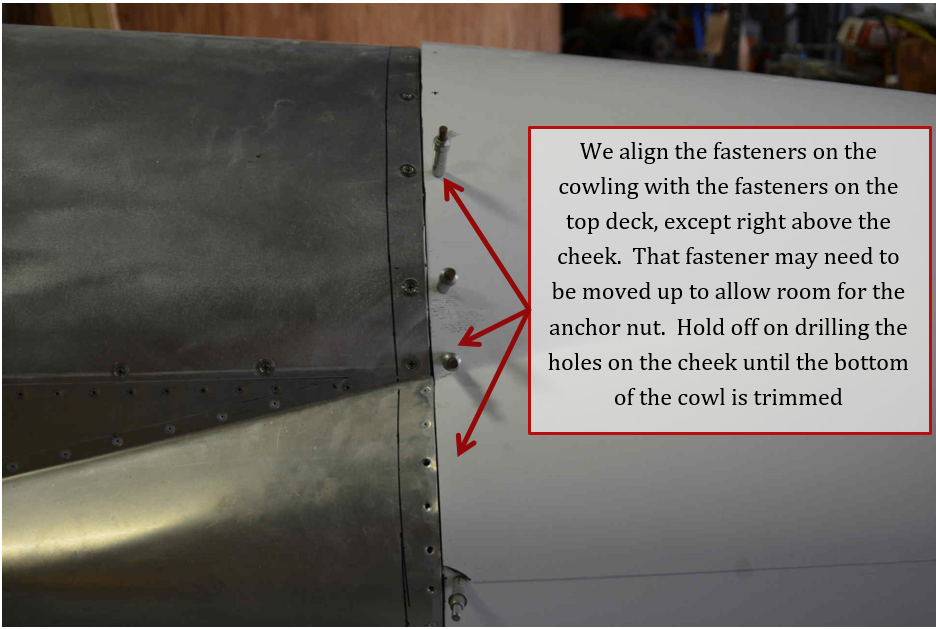
You can now mark for holes around the top. We use the same pattern as the fasteners around the front deck, except by the cheek line where we had to move it up to fit the flange tabs. While not shown, you will also want a fastener just above the cowling split line and one just below the cheek line. Again, if the cowling is not flush with the skin, you can add some fiberglass inside the cowling as shims.
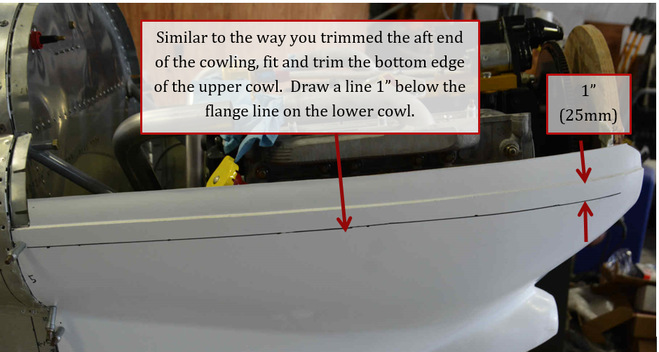
Trim the top cowling along the bottom edge using same technique as the aft edge of the cowling.

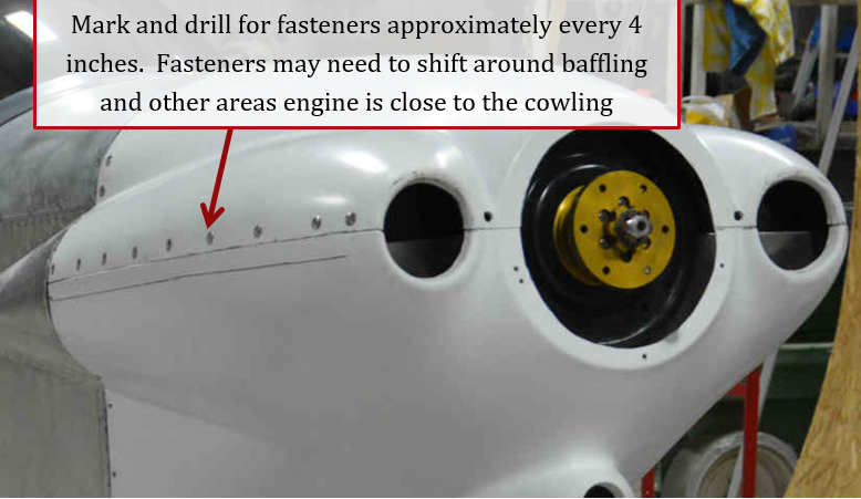
Fasteners should be about every 4” along bottom edge. Check where the engine components or baffling is close to the cowling, and shift fasteners as necessary to miss these areas.
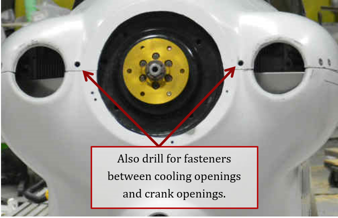
Also, 2 screws/fasteners are needed on the front between the cooling inlets and the opening for the crankshaft.
Fasteners
Many different styles of fasteners can be use. On the prototype we use 8-32 counter sunk screw,and finishing washers with nut plates for the upper and lower cowl. With small inexpensive and powerful electric screw guns being prevalant ,removing htre 25 screw of the cowling is a 2 minute process. On N515XP We did not install a oil door because due to the ":experimental", and "testing" environment we remove the top cowl for inspection after virtually every flight. The install shown above uses the very high quality fasteners from Skybolt. They large size is shown , but we suggest the smaller size Skybolt fasteners now.These are quick and easy enough to remove that a oil dipstick/ fill door may not be necessary.
Our current suggestion is screws and nutplates to secure the lower cowl , with the Small size fasteners fromm Sky bolt around the top.
Oil Cooler door
A If top cowl is the be held in place with screws we suggest a oil filler door be added in the appropriate postilion. The hidden hinge From ACS works well and much information and ideas can be found online for a nice oil door installation.
