NOTE: Some portions of the elevator trim installation require the fuselage side skins to be clecoed in place. The actual mounting of the bracket to the throttle quadrant is easier with the skins off, but can also be done with the skins on.
NOTE: The elevator friction bracket - Part Number P8513 - is a part you will need to fabricate from 6061T6 aluminum .032 thickness. A template to make this part can be found here - https://flywithspa.com/documentation/panther/P8513.pdf
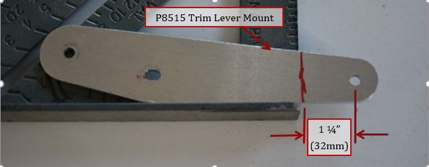
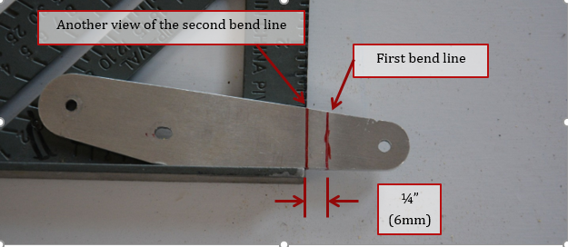
1. P8515 - Trim lever mount. Draw a line approximately 1 ¼” from center of hole as shown below. Make sure to follow the instructions below with the directions of the bends, or the joggle will be in the wrong direction. Check pictures of bracket being mounted later in this section to see the joggle.
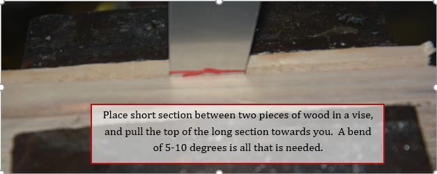
2. Place in vise with the short section between 2 pieces of wood. Pull top of bracket towards you. You only need about 5 to 10 degrees of bend.
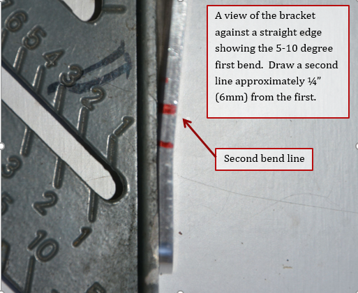
3. This picture shows the first bend against a straight edge. Draw a line approximately ¼” from behind the first, this will be the location of the second bend.
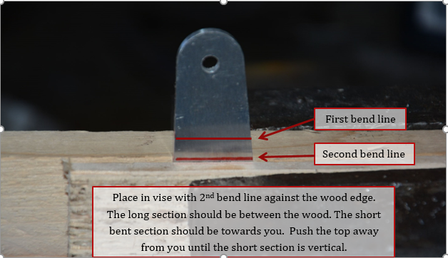
4. Place bracket back in the vise as before, but with the long section in between the wood. The bent short section should be facing you. Once clamped in position, push the top of the bracket away from you.
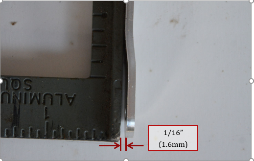
5. This shows what the joggle will look like against a straight edge. Bends can be flattened or re-bend slightly to obtain the 1/16” joggle.
6. If not already done - fabricate the friction lever bracket. A template for this can be found here:
P8513 Friction Lever Bracket Template
URL = https://flywithspa.com/documentation/panther/P8513.pdf
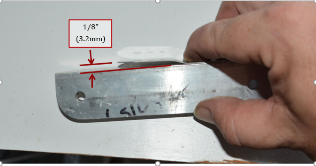
Form a joggle on the trim lever friction bracket in the same manner as before
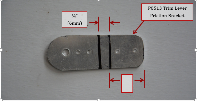
7. Joggle should be 1/8”
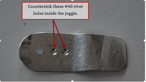
8. Countersink 2 #40 rivet holes in orientation as shown (inside of the joggle)
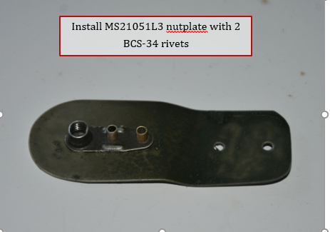
9. Install nutplate with 2 BCS-34 rivets.
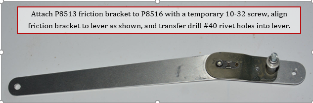
10. Thread a temporary 10-32 screw through the trim lever and into the nut plate. Align bracket as shown and transfer drill #40 holes into trim lever.
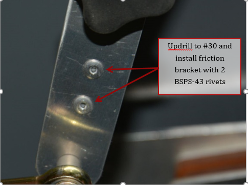
11. Updrill to #30 and install 2 BSPS-43 rivets.
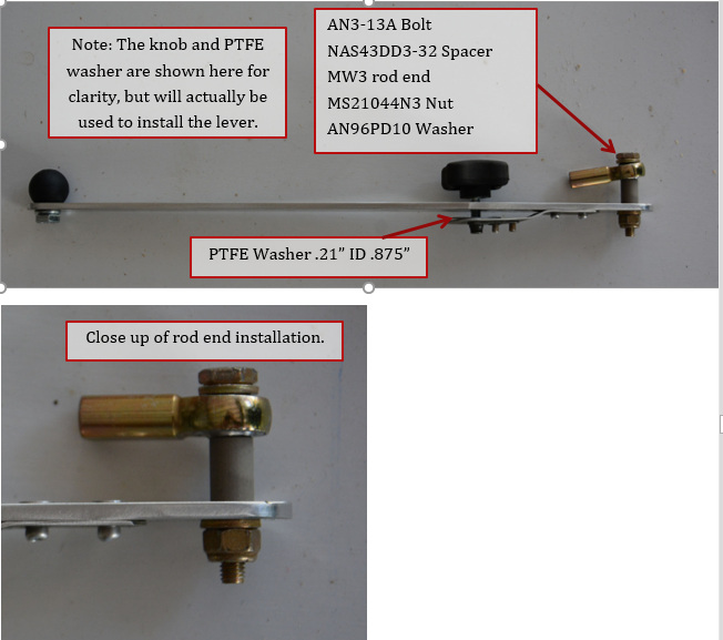
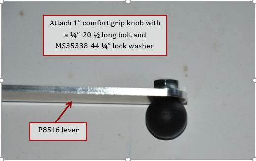
12. Attach knob to trim lever.
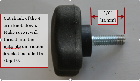
13. Cut the 4 arm friction knob shank to length
14. Install rod end on elevator trim lever. It is easier to install the rod end with the lever out of the aircraft if you have the fuselage side skins installed, trim cable can also be screwed into the rod end now if you want. The friction adjust knob and PTFE washer are shown installed here for clarity, but will actually be used to install the lever on the mount.