1. With an assistant, install the left wing. Start both wing pins into the left wing, but not past the forward edge of the spar. Since the guides have not been adjusted yet, the assistant will need to hold the wing in position to slide the pin in. Next install the right wing and continue pushing the pin through the right spar and into the forward fuselage hole. This will be tight and take some wiggling of the wing and the pin. Setting and checking the incidence now with both wings in position will help when adjusting the forward spar pins.
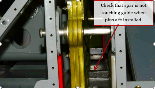
2. With the pins installed, check that the wing spars clear the lower center nylon guide. The guide may need to be filed down to be just below the spar, but not touching

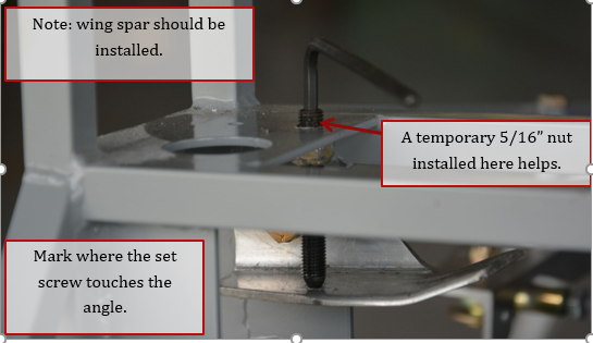
3. Move both of the upper guide angles down until they touch the upper surface of the spar. Adjust the nut on the set screw, until the nut is against the bottom of the upper spar box plate, and the point is just touching the surface of the angle. Tighten a temporary 5/16-24 nut on top of the spar box to hold the set screw square to the surface of the upper spar plate. Mark the center of the set screw point on the upper guide angle.

4. Remove the angles and lightly drill at the center point with a ¼” drill bit. You want to create a depression on the angle, to keep the set screw from moving around while adjusting it. Do not go more than about halfway into the angle.
5. Replace the angles, and lightly snug both angles down using a MS21044N4 nylock nut and washer AN960-416 washer on the AN4 bolts that attach angles to spar box.
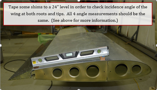
6. Tape some blocks of wood to a 2’ digital level, and check the incidence angle of the top surface of the wing. The height of the shims does not matter, as long as the level rests flat on them, and the level clears the curvature of the wing. It is best if the shims do not sit on rivets, but as close to the front spar and rear spar as possible. We are not worried about the true incidence angle of the wing as the forward wing pins and the 2” rear spar shims set that angle. We do want to check that the wings don’t have any twist in them. Check the angle at the tips and close to the root of both wings. Keep the level in the same orientation and with the same shims at the same spot on the level. If the shims come loose, start over. Let the level sit and stabilize for a minute or so. The calmer the air the easier it is to be consistent. Writing the measurement with a sharpie on the wing comes in handy, acetone will take it off quickly. Having the fuselage nearly level makes it easier to keep the level on the wing.

7. If all 4 measurements are the same, you did a great job building the wings straight and can proceed to section 5.3.3 and adjust the front spar guides so the wing pins can be removed easier.
8. If both measurements on a wing are the same, but different on one side than the other, add shims below the rear spar, or file down the shims until both sides are the same. If you have to adjust the shims more than a 1/16”, you need to look closely at your setup as there is probably a problem somewhere in the wings. One trick is to carefully use a jack or sawhorse and shims carefully raise or lower the rear spar until the angles are the same. But be extremely careful, because it is also a very good way to destroy a wing if the rear spar is jammed against the spar box. With the wing held in place, it is easier to adjust the height of the rear shim to the proper height.
9. If the measurements are different between root and tip on a wing, then there is some twist that has been built into the wing, or possibly the rear spar attach plate is hitting the top of the rear spar box, forcing a twist in the wing. With the fuel tanks removed, and only clecos in the forward portion of the inboard wing skins, the wing can twist approximately .1 to .2 degrees.
10. If after the above checks, you are not able to make the angles agree within .1 to .2 degrees, call us for help.
