
1.Clamp P6506 in place flush with aft face of bulkhead 5. Mark a line on the Vertical tail upper mount P6506. There are 2 different sizes use the picture that fits the dimensions of your mount. Older mounts were 1 1/8” tall, newer mounts are 1 3/8” tall.
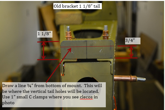
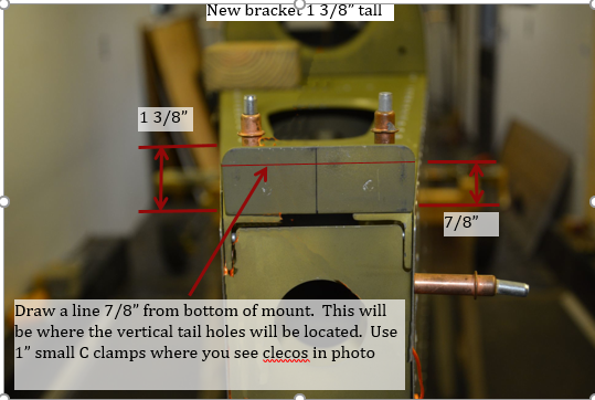
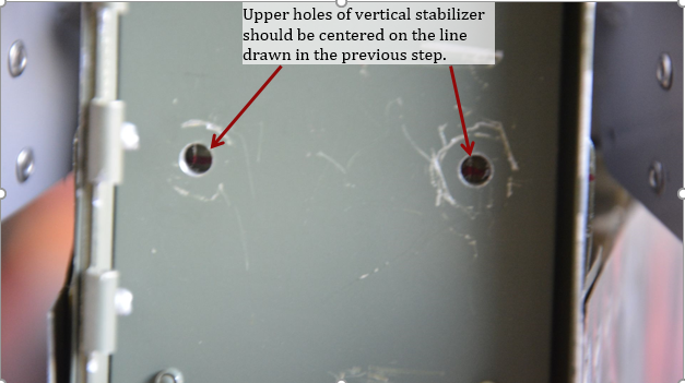
2.Place vertical stabilizer on the fuselage, so that the upper 2 mounting holes are on the line drawn in the previous step. Clamp VT in position.
Note: You may need to loosen the clamps on P6506 so it can rest tight against vertical stab spar.
3.The bottom of the skin at the leading edge of vertical stabilizer may need to be trimmed in order for the vertical stabilizer to fit properly. Until the forward spar is attached, the vertical stabilizer is rather flexible, in a later step we will check for straightness and re-trim the gap, so only trim enough to get the vertical stabilizer to fit.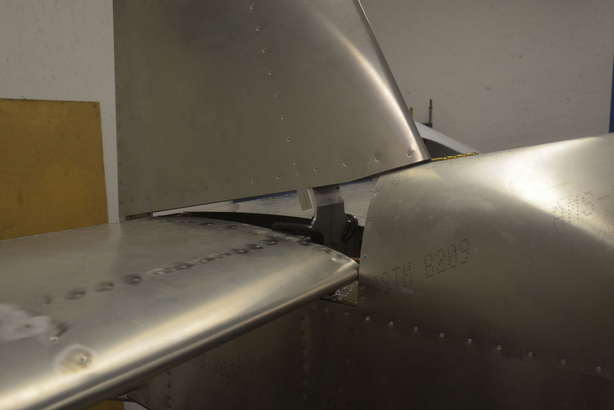
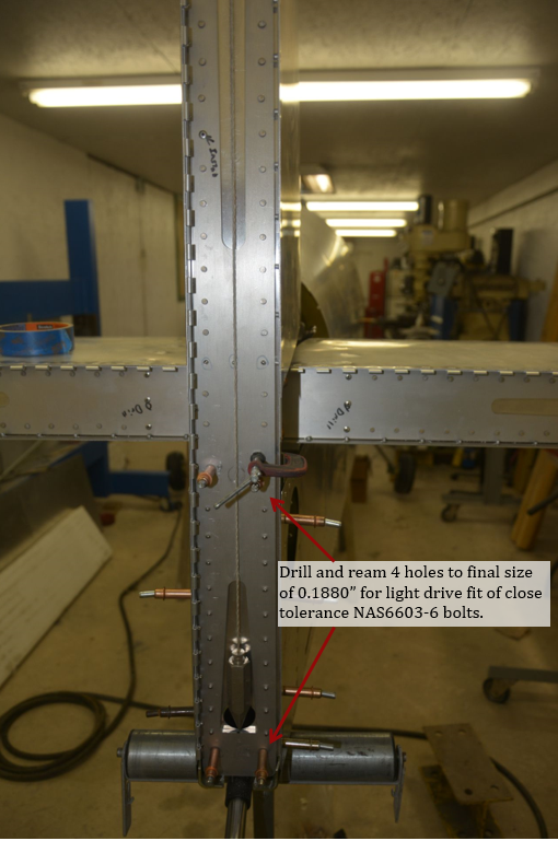
4.Hang a plumb bob from the top of the vertical stabilizer centered on the center rivet of the upper rib. Let it hang free, and adjust vertical stabilizer until the string is centered at the bottom. Once positioned, transfer drill #30 holes from vertical stabilizer into aircraft structure.
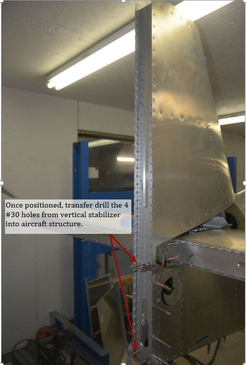
5.Using a straight edge check the hinge line. It should be straight, if not raise the leading edge as necessary, or trim more off the bottom of the leading edge until it is straight. There should be 1/8” to 3/16” gap between the turtleback and the bottom of the vertical stabilizer.
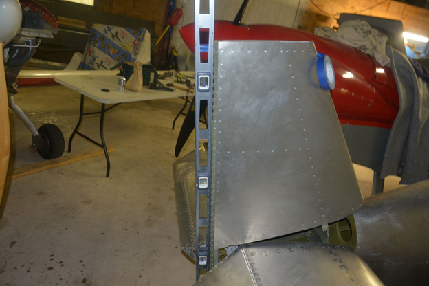
6.Place a shim between the horizontal and vertical stabilizer, this will come in handy later. If you don’t have a right angle drill, mark this position.
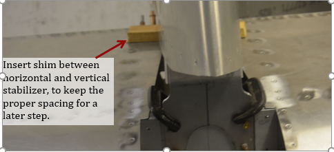
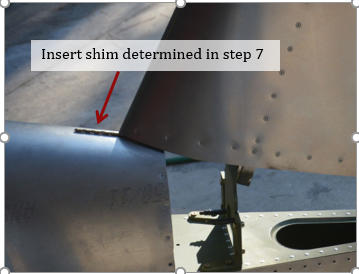
7.Clamp the forward spar of the vertical stabilizer in place, and align center mark on the vertical stabilizer spar to the center mark on the horizontal stabilizer. Also find the size of shim to fit between turtle back and the vertical stabilizer. A drill bit worked for me. This is important if you don’t have a right angle drill.
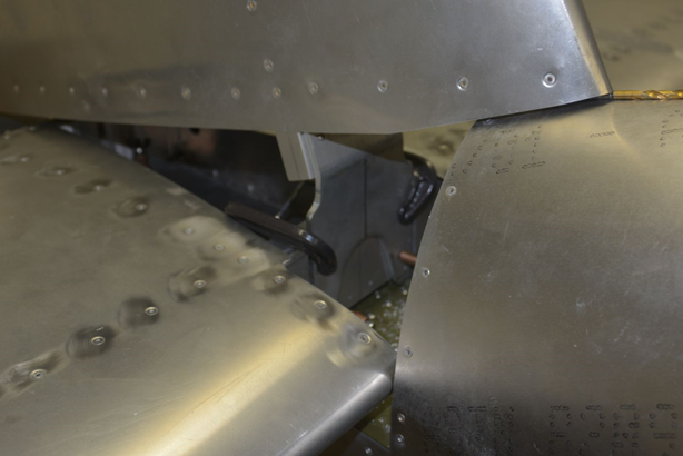
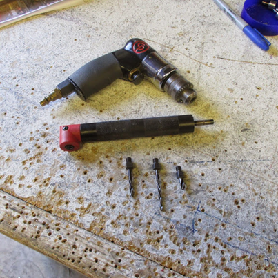
8.If you have a right angle drill similar to the ones shown below, you can use it to transfer drill the #30 holes to the vertical stabilizer. It is suggested to have a second person to help check that you are drilling square to the spar. Try to minimize drilling at an angle. Cleco the vertical stabilizer to the horizontal stabilizer spar. If you don’t have a right angle drill go to the next step. Otherwise, you can skip to step 13.
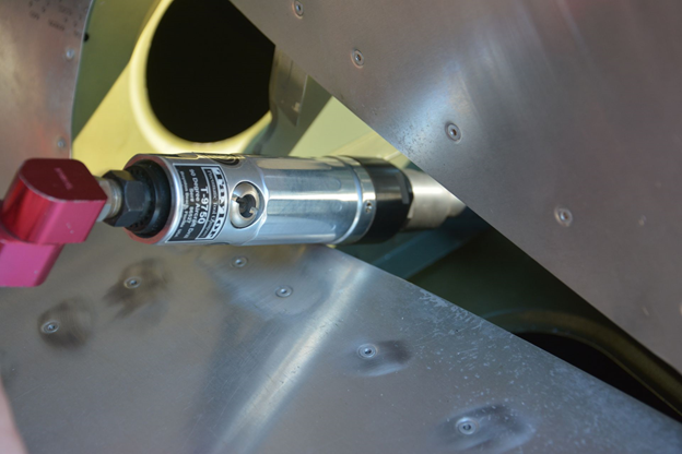
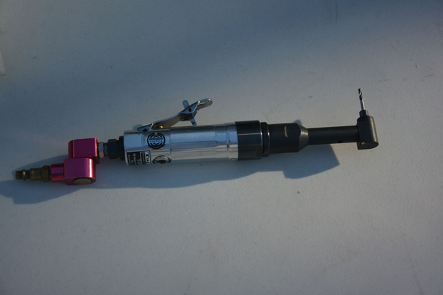
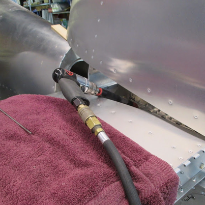
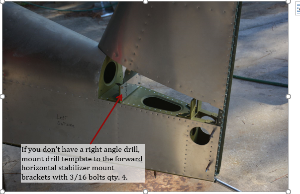
9.The following steps are only for use if you do not have a right angle drill. Remove vertical and horizontal stabilizer, and install the drill template made in the horizontal stabilizer installation section to the forward horizontal stabilizer mounting brackets using some 3/16” bolts. Mount vertical stabilizer to rear spar using clecos. Clamp to the template temporarily using clamps.
10. Insert shim determined in step 7 between turtle deck and vertical stabilizer.
11.Align center mark on vertical stabilizer to one drawn on the template. And clamp in position. Note: this was a test, and had clecos installed instead of clamps, this is a preproduction vertical stabilizer, and has 2 extra holes, and 2 other holes in an incorrect position.
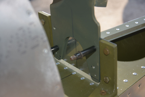
12.Transfer drill the #30 holes from the template into the vertical stabilizer forward spar.
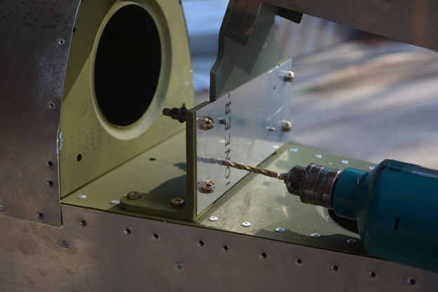
13. Once pilot holes have been drilled, the vertical and horizontal stabilizer can be removed from the aircraft and set on a table to finish drilling and reaming the holes to the final size. Be sure to not disturb the P6506 bracket that is clamped to the longerons.
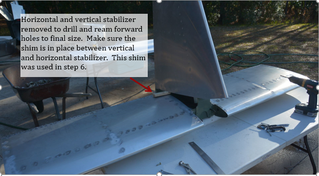
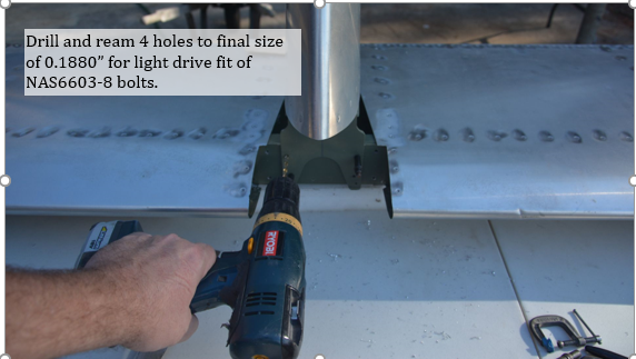
14. Drill and ream holes for close tolerance bolts using drill #16 and reamer .1880” for NAS6603-8 bolts. Holes should be a light drive fit for the bolts.
15. With P6506 firmly clamped in place drill and cleco the forward 4 holes #30. Then drill the aft 2 holes for NAS6603-3 bolts.
16. Permanently install P6506 with 4 BSPS-44 rivets and two NAS6603-3 bolts, nuts and washers as needed.
Note: While the fuse is still level you may consider rigging the elevator travel and adjusting stops at this time. See the Rigging BM for more information
