1. The pitot tube disconnect is optional and intended for builders who plan on folding their wings frequently. If you plan on folding your wings only occasionally a straight quick connect fitting similar to the angled ones shown might be better. These fittings can be found at your local hardware store for icemakers. In which case, the printed stem and base will not be used.
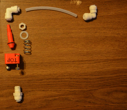
2. Below are the parts needed for the pitot tube quick disconnect option. In addition to the printed stem (with O-ring, spring, washer, and nut installed), and the base with rubber washer, you will need 2 right angle quick disconnects, and 1 1/8” male NPT to quick connect fitting, and a piece of ¼” od tubing (same as used for pitot line in wing). The quick connect fittings can be found at your local hardware store for icemakers, they have a sleeve around the tube that pushes in, and will allow you to release the tube. There is an O-ring internal to the fitting that seals around the tube or stem.
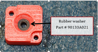
3. The base is a printed part, with a rubber washer installed. Make sure this washer is still in the base. Replacement washers are 0.078” thick 0.195” ID 0.438” OD Neoprene washer, McMaster Part number 90133A021.
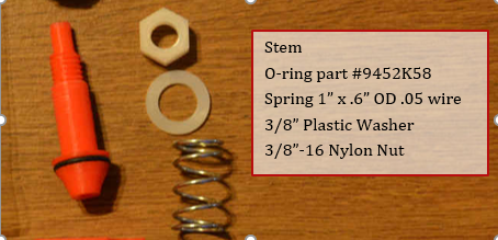
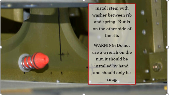
4. Make sure the rubber O-ring on the stem is installed. The nut should only be installed by hand, never use a wrench on it, stem is likely to break if nut is tightened to tight.
5. On bottom of rib 1, left wing, measure aft 8 ½” from main spar stiffeners.
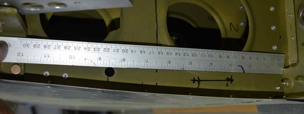
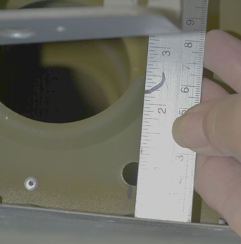
6. Measure up from skin ¾”. Drill a 7/16” hole in wing rib for the stem.
7. Insert stem in rib 1 as shown, the spring and washer is outside of wing. Carefully push stem through hole until threads are no longer visible. Nut should be screwed on by hand until snug, do not over tighten or use a wrench as stem will break.
8. Quick connect fittings and piece of tubing can be used to connect the stem to the pitot line previously installed in the wing. Tubing should be cut to length to allow the stem to freely move in and out without kinking the tube.

9. Install wing in fuselage, with wing nearly against the fuselage, place the base on the stem. The base has the word “TOP” embossed on the top, make sure this points up, the text can be highlighted with a sharpie marker to make it easier to see. Push the wing the rest of the way in, until base is held against the fuselage by the spring loaded stem. Note: the white stem and base are prototype units, the final ones are red.
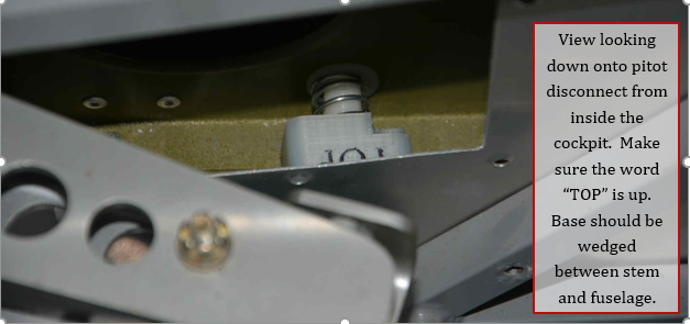
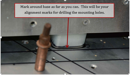
10. View looking up from under left wing. Turn base until parallel with bottom of wing. Mark around the bottom of the base as much as you can.
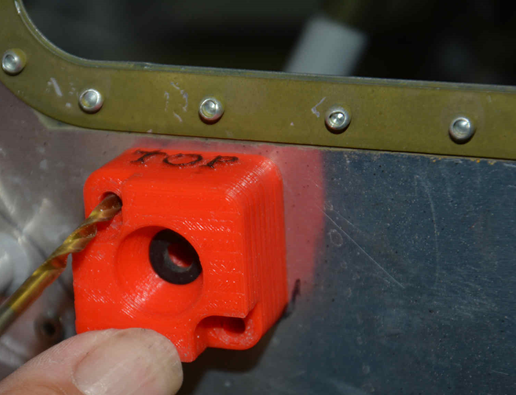
11. Hold base in position, and using a #19 drill bit, drill through holes in base into the skin.
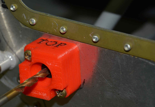
12. Insert MS35206-249 screws temporarily to help hold base in position. Carefully drill through center hole using a 3/16” drill bit. Try to avoid damaging the hole in the base. One tip is to mark the hole by briefly drilling, then remove the base and continue drilling at the location marked by the bit.
13. Enlarge center hole to 3/8” diameter minimum.
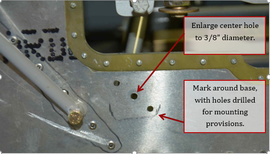
14. Install base using MS35206-249 screws
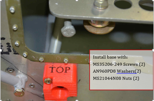
15. Inside fuselage check that the threaded hole in the base is completely visible through hole in fuselage skin. If not, you can enlarge the hole slightly until completely visible.
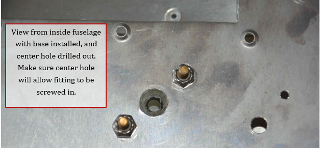
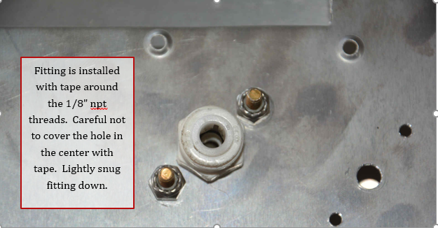
16. Install fitting with thread sealant tape, careful not to overtighten fitting.
