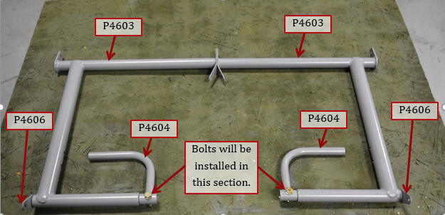
1. Layout of how rudder pedals are assembled. Insert torque tube through tube at bottom of rudder pedal with master cylinder mounting tab outboard. Slide brake pedal onto torque tube. Some powder coating may need to be removed for parts to fit. Lightly prime any bare steel. The fit should be tight between brake pedals and torque tube, and the torque tube should easily rotate inside of rudder pedals.
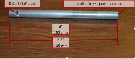
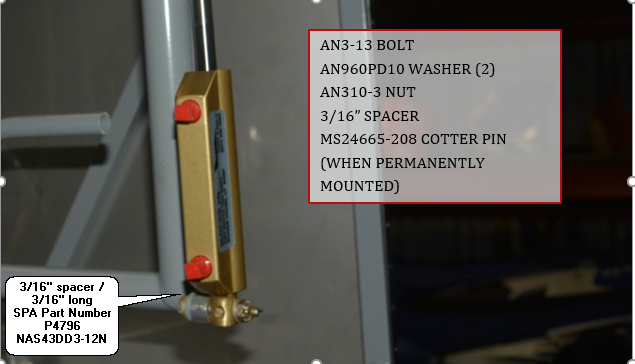
2. Make 2 of the master cylinder extension tube as per picture below. They are made from ½” OD .120” wall 6061 tubing that is available from aircraft spruce. If you ordered your hardware kit from SPA this tubing is included. Cut to length, tap one end to 5/16-24 thread, and drill a 3/16” hole through the tube on the other. These extensions are designed for the MATCO MC-4 master cylinder that SPA recommends and sells. Any other master cylinder will require different extensions.
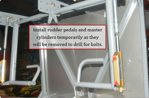
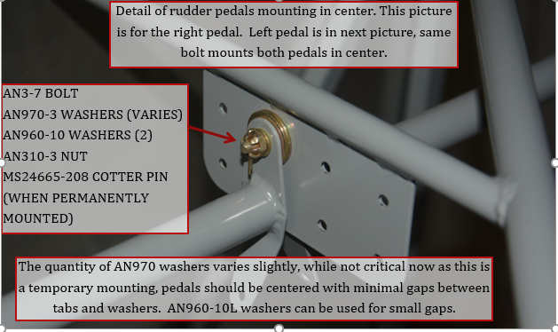
3. Install rudder pedals and master cylinders temporarily as shown below. The positions are dependent on what best fits you. The master cylinder extension should always be in the same row of holes, but one hole behind the rudder pedals. That leaves 6 positions for the rudder pedals. Pilots with larger feet will probably want to use the upper holes. Pilots with smaller feet will want to use the lower holes. This should accommodate the majority of pilots. If you feel the rudder pedals are still too high, you can make a sub-floor on the bottom of the fuselage to rest your heals on.
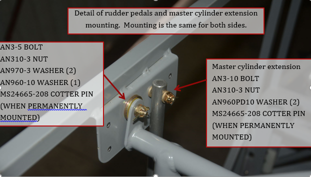

4. Install master cylinder by threading extension and locking nut all the way onto master cylinder and back off 3 turns (to allow for fine adjustment later). Tighten locking nut against extension. Install
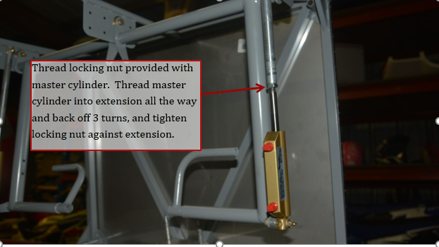
5. Install bolt to attach master cylinder to torque tube.
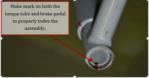
6. It is time for you to get in the airplane, and with the rudder pedals hanging straight down, determine the best angle of the brake pedal for your foot. Rotate brake pedal on torque tube for the best fit. Have an assistant mark the end of the torque tube and brake pedal as an index mark. Only one pedal needs to be marked as the fixture for drilling will set the other one the same.
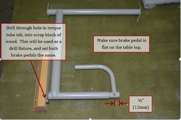
7. Remove the rudder/brake pedal assemblies from the aircraft. Place the marked assembly on a bench, with the brake pedal flat against the bench top. Place a scrap piece of wood next to the tab for the master cylinder (rectangular shaped scrap is better than the one shown. Drill through hole in tab with a 3/16” drill, and insert a bolt through tab into the wood. This will hold the tab in the correct position for drilling. Make a mark on the brake pedal ½” from end and on the center of the tube for the cross bolt.
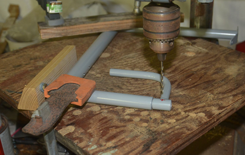
8. Clamp the assembly on a piece of plywood mounted to your drill press. This is how I clamped mine, but yours will vary depending on your drill press. I drilled a #30 pilot hole through both pieces, then used a 3/16” drill bit. You want a tight fit for the AN3-10 bolts.
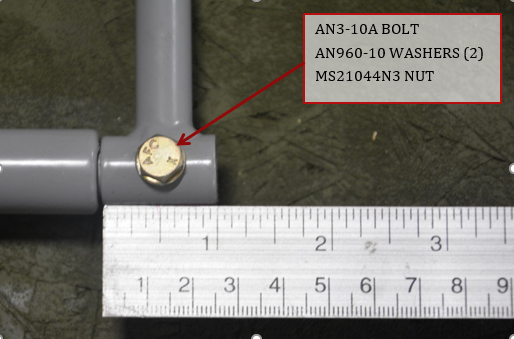
9. Install AN3-10A bolt through brake pedal, using AN960-10 washers (2) and MS21044N3 nut.
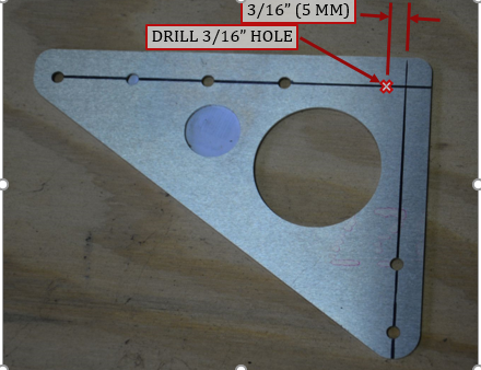
10. Drill 3/16” hole in rudder return spring plate as shown below.
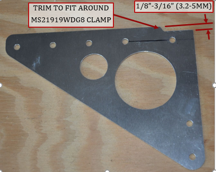
11. Trim edge of rudder return spring to fit around the MS21919WDG8 clamp. Clamp can be seen in next pictures.
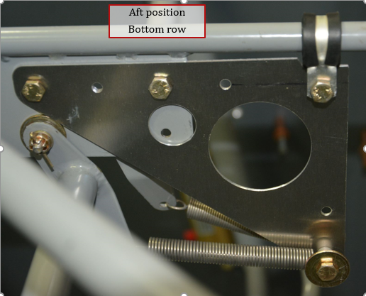
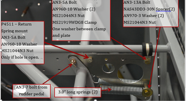
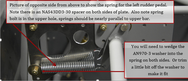
12. Reinstall rudder pedal assemblies as in steps 3-5. You will also install the rudder return spring plate. If installing rudder pedals in upper row of holes, the rudder pedal plate should be installed with the rear most hole under the rudder pedal center bolt as shown below. If pedals are installed in one of the 2 rear positions, install AN3-5A bolt in the forward hole. If installing pedals in bottom row see step 11. Pictures show temporary nuts in place, locking MS21044N3 nuts should be used. AN970-3 washer is a little to large, it can be wedged into the spring, or trim on edge flat to fit.
13. This step is for rudder pedals in the lower holes, hardware same as above, but another AN3-5A bolt is used. Pictures show temporary nuts in place, locking MS21044N3 nuts should be used. Springs shown below are the old version.

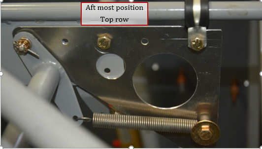
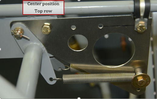
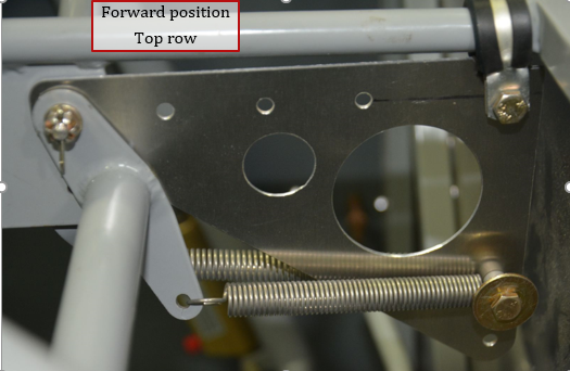
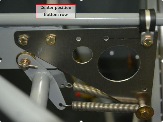
14. The following 6 pictures show the 6 different positions of the rudder pedals and how the return spring plate is positioned. Direction of bolt heads does not make any difference. Springs shown below are the old version.