
1. Make sure the fuel tank has been fitted to the wing before this step. It does not have to necessarily be rivet or screwed in place yet, although it can be. The tank in this photo was clecoed in position. The fuselage skins should also be clecoed securely in place.
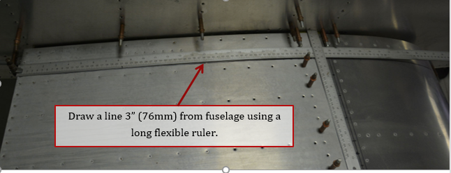
2. Draw line parallel to the fuselage 3” outboard of the fuselage using a long flexible steel ruler. Continue the line to the leading edge of the fuel tank. Note, the fuselage starts to narrow in the area of the fuel tank, so the distance between the fuselage skin and the line drawn will increase as you get to the leading edge of the tank.
3. The curvature of the tank might be too much for ruler to easily wrap around at the leading edge of the tank. If this happens, stop the line where the curvature is too great.
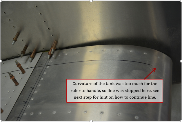
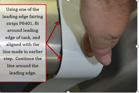
4. Using the leading edge fairing P8401, align the edge to the line drawn previously, and use the fairing as a straight edge around the leading edge of the tank, and onto the bottom of the fuel tank, back to the fuel drain fitting. It is helpful to clamp the fairing in place around the leading edge.
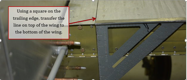
5. At the trailing edge, use a square and transfer the line drawn previously to the bottom surface of the wing.
6. Measure distance between the root of the wing and the mark made in the previous step. Mark and draw a line the same distance away from the root of the wing around the main spar area.
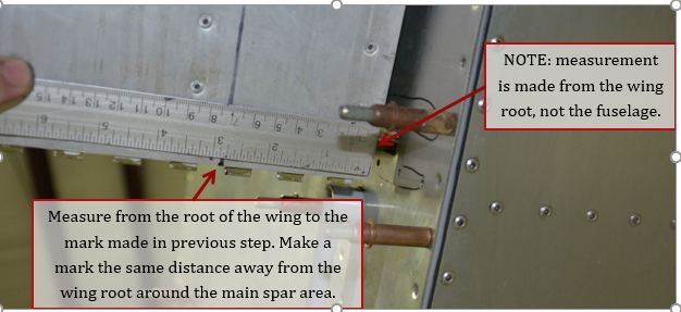
7. Using a flexible ruler, draw a line connecting the 2 marks made. Because of the dihedral and the curvature of the wing, this will not be a constant distance between the line and the fuselage.
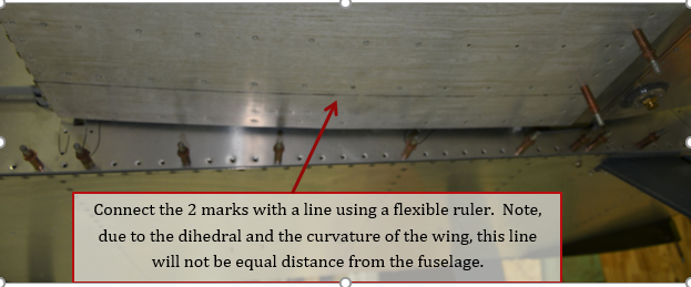
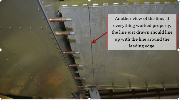
8. Another view of the line bottom surface, continue the line to the fuel drain. If everything worked properly, the line just drawn should be in line with the line drawn around the leading edge of the tank.
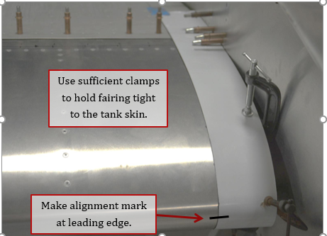
9. Tape and clamp the leading edge fairing in place. Tape alone will not hold the fairing in place especially around the leading edge of the tank. Small C clamps work well to clamp the fairing to the skin of the tank.
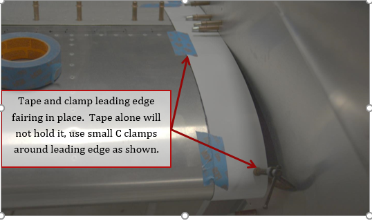
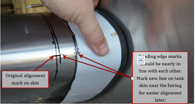
10. Use sufficient clamps to hold fairing tightly to the skin of the tank. Make a mark at the leading edge of the skin for future alignment purposes.
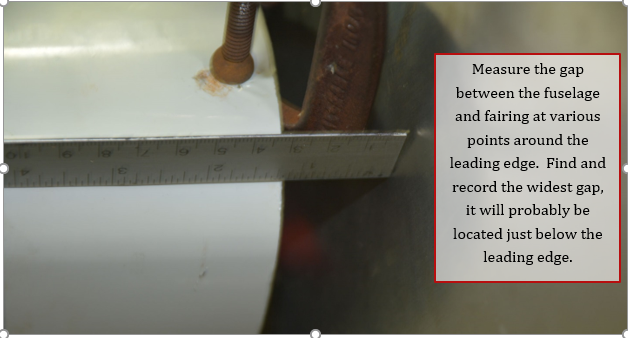
11. Measure in various places around the leading edge to find the widest gap between the fuselage skin and the edge of the wing root fairing. Record the measurement of the widest gap. The widest gap will probably be located just below the leading edge.
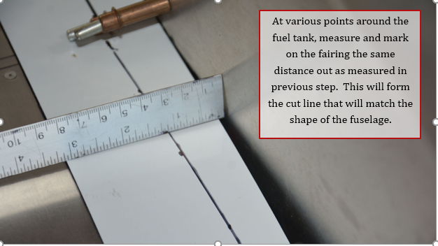
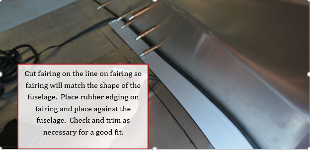
12. At various points along the length of the fairing measure out from the fuselage the same distance measured in step 11. Connect the points with a line. This will be the cut line so the fairing matches the shape of the fuselage.
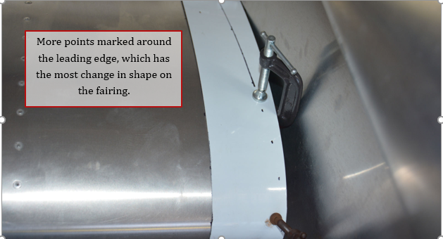
13. Another view of the points marked to form the line around the leading edge of the tank.
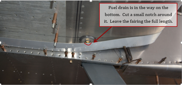
14. On the bottom, the fuel drain gets in the way. Cut a notch around the fuel drain itself, not around the doubler for the drain. This will allow the fairing to get closer to the skin of the tank. Continue measuring and marking line along the length of the fairing. Note, the fairing will be cut approximately 1 ½ holes aft of the fuel tank skins, so it is not necessary to be very accurate aft of this point. Leave the fairing the full length at this point however, as it will allow you to adjust later if necessary.
15. Cut the fairing down to the line drawn previously. Check fit all the way around the fairing, adjust/trim as necessary for best fit. Place rubber edging around the cut edge of the fairing and place against the skin.
16. Leading edge mark should be in line with mark made previously on leading edge. However, it can be adjusted for the best fit now, remark if necessary.
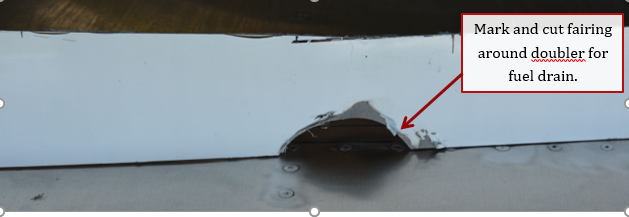
17. Mark and trim around doubler for fuel drain on bottom side of the fairing.
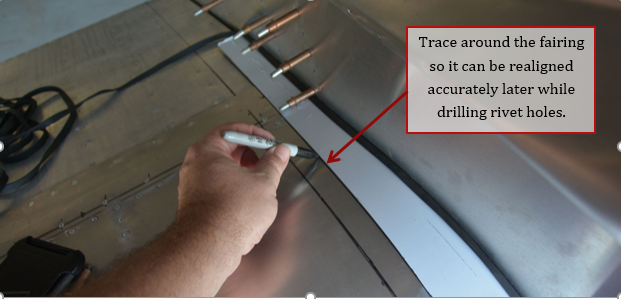
18. Trace around the fairing on the wing, this will serve as the alignment line when reattaching the fairing to drill the rivet holes.
19. Align new hole with center of the hole in the fuel tank. New hole should be approximately 5/16”-3/8” in from edge, make sure you do not drill into the tank.
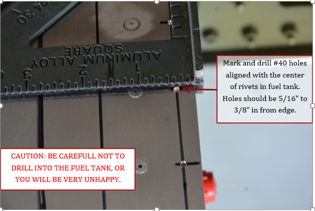
19. Continue marking and drilling #40 holes all the way around the edge of the tank skin. Additional holes can be drilled around leading edge if necessary to hold the fairing in place against the tank.

20. Pull the wing out of the fuselage slightly, around 10” or so, be sure spar is supported by the upper middle guide block in the fuselage. Re-clamp fairing to the tank using alignment lines previously drawn.
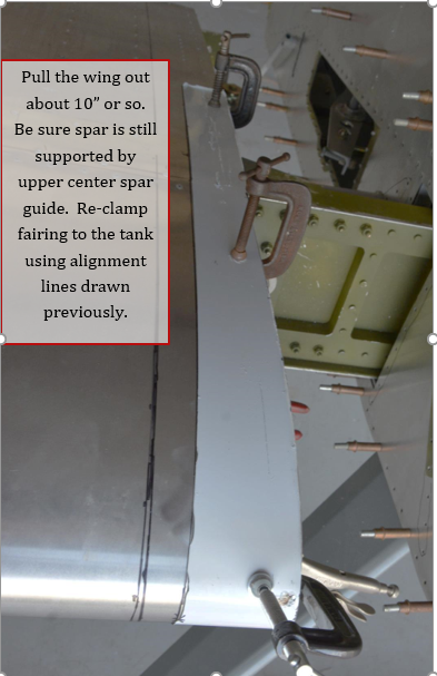
21. There are 3 ways to transfer, drill the holes in the tank to the fairing, the easiest most accurate way is with a small right angle drill similar to what is shown in this picture.
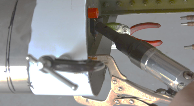
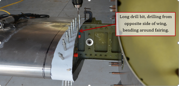
22. The next option is to use a 12” to 16” long #40 bit and with the bit slightly bent, drill the hole. While this works, be careful not to oblong the hole or allow the bit to walk away from hole.
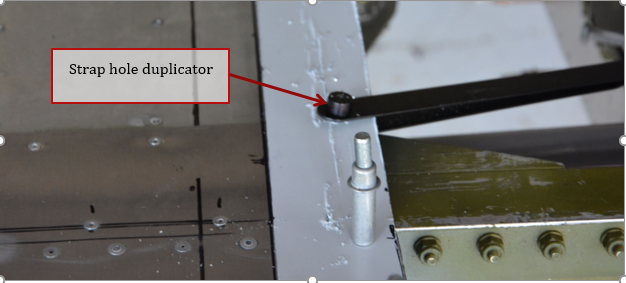
23. The final option is to use a strap hole duplicator, same as the one used for the flap doubler. The problem with this is the strap holds the fairing away from the skin and could cause the holes to be off slightly, especially around highly curved surfaces.
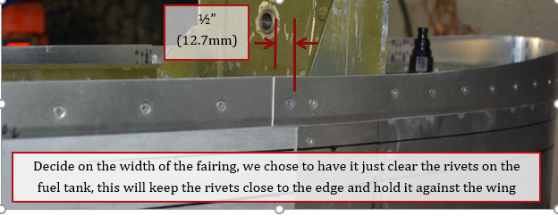
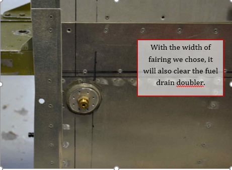
24. The final width of the root fairing is up to you; we chose to cut the strip down so it would just clear the row of rivets in the fuel tank. For builders using protruding head rivets, this would work the best. For flush rivets, it doesn’t make much difference, although having the row of rivets close to the edge will help hold it down better, especially if the edge is flanged slightly as shown. Cut the strip off about ½” aft of the first rivet behind the spar flange on both top and bottom. Do not rivet in place until all strips have been cut and drilled.
24. Temporarily install fuel vent line. Mark on lower edge of fairing the location of the vent tube and edge of tank skin. Drill a 5/16” hole so edge of hole will clear the tank skin.
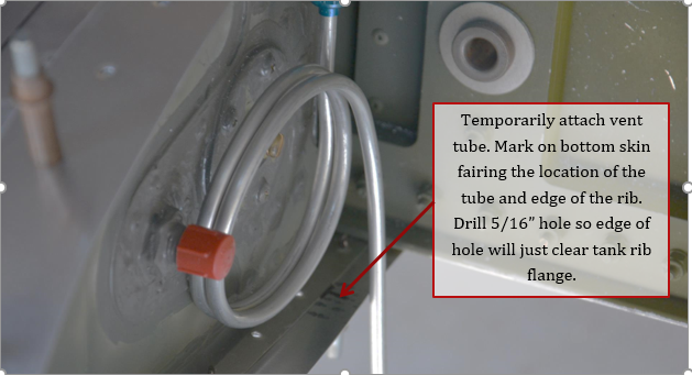
25. Check fit of vent line. When satisfied, it is safest to remove the vent and reinstall after paint. Be sure to keep lines and fittings capped to keep bugs and debris out.
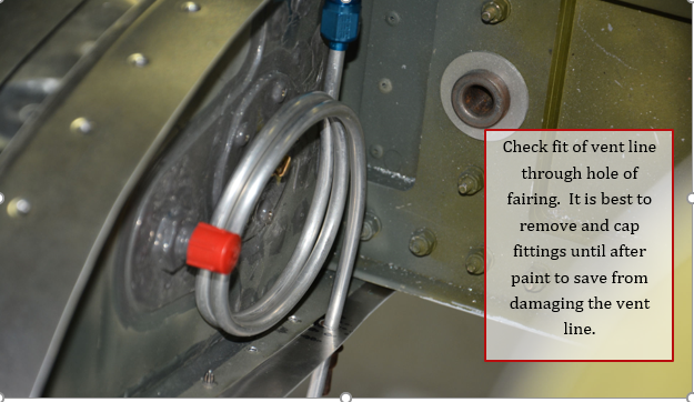
26. View from underside showing how cut strip clears the fuel drain if cut down in width to clear the first row of rivets on the fuel tank, and shows the finished hole for the vent line.
27. Cut the strip P8402 for the top right wing to the same width as the tail of the piece you just made for the leading edge. With wing pinned in place, and rubber edging wrapped around the edge of the new strip, position strip against fuselage, with the front under the leading edge strip, and butted up against the fuel tank skin. Transfer drill the holes in Rib 1 of the wing into the strip using the strap duplicator and long #40 bit as shown below. Cut the aft end of the strip off flush with the trailing edge of the wing. Note, if holes in rib 1 are already #30, use #30 strap and #30 bit.
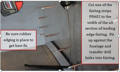
27. Repeat with the bottom strip
28. Up drill all holes to #30, if not already done. Deburr/dimple as needed.
29. If fuel tank has been installed, rivet strips in place using BSC-42 or BSPS-42 rivets depending if you want flush or protruding head rivets.
30. Repeat for the left wing
